.....Read More

Frequently Asked Questions

What are the different types of precision measuring tools?

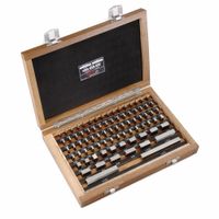
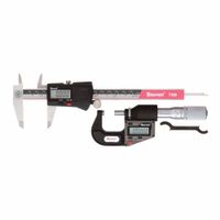
Precision measuring tools are instruments designed to provide highly accurate measurements, crucial in fields like manufacturing, engineering, and quality control. They minimize human error and ensure consistency. Here are some common types: * **Calipers:** These are versatile tools used for measuring internal, external, depth, and step dimensions. Common types include: * **Vernier Calipers:** Rely on a vernier scale for precise readings. * **Digital Calipers:** Feature a digital display for easy reading and often offer unit conversion. * **Dial Calipers:** Use a dial indicator for reading measurements. * **Micrometers:** Used for even more precise measurements, typically for small distances or thicknesses. Types include: * **Outside Micrometers:** Measure external dimensions. * **Inside Micrometers:** Measure internal dimensions. * **Depth Micrometers:** Measure the depth of holes or steps. * **Dial Indicators/Test Indicators:** These tools measure small linear distances or deflections. They are often used to check for runout, flatness, or concentricity. * **Height Gauges:** Used to measure vertical distances from a reference surface, often in conjunction with a surface plate. * **Gauge Blocks:** These are precision-ground steel or ceramic blocks with highly accurate dimensions, used as reference standards for calibrating other measuring tools or setting up machines. * **Protractors and Angle Gauges:** Used for measuring and setting angles with high accuracy. * **Profilometers/Surface Roughness Testers:** Measure the texture and roughness of a surface.Each of these tools plays a critical role in ensuring the accuracy and quality of manufactured parts and assemblies.

How do you calibrate a micrometer?

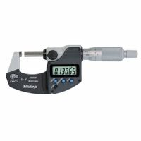
To calibrate a micrometer, you generally need a set of gauge blocks or a standard rod. First, clean the anvil and spindle faces thoroughly. Then, close the micrometer carefully until the anvil and spindle faces meet. If it's a 0-1 inch/0-25 mm micrometer, the thimble should align exactly with the "0" mark on the sleeve. If it doesn't, use the spanner wrench provided with the micrometer to adjust the thimble until the lines align. For larger micrometers, or to check accuracy across the range, use gauge blocks. Place a gauge block of a known dimension between the anvil and spindle. Close the micrometer until it lightly grips the gauge block, and then check if the reading on the micrometer matches the known dimension of the gauge block. If there's a discrepancy, adjust the micrometer using the spanner wrench as needed. It's recommended to check at several points within the micrometer's range (e.g., 25%, 50%, 75% of the full range) to ensure consistent accuracy. Always store the micrometer in its case to protect it from damage and dust.

What is the difference between a caliper and a micrometer?

A caliper and a micrometer are both precision measuring instruments, but they differ primarily in their accuracy, measuring range, and application. A caliper is a versatile tool used for a wider range of measurements, including external dimensions (outside diameter), internal dimensions (inside diameter), depth, and step measurements. They typically have a lower accuracy compared to micrometers, often in the range of 0.02 mm to 0.05 mm (0.001 to 0.002 inches). Calipers are generally quicker to use and are suitable for general workshop or manufacturing applications where extreme precision isn't always critical. A micrometer, on the other hand, is designed for highly precise measurements of external or internal dimensions. They achieve much higher accuracy, typically to 0.01 mm (0.0004 inches) or even 0.001 mm (0.00004 inches) for digital models. Micrometers have a more limited measuring range than calipers and are often dedicated to a specific range (e.g., 0-25 mm, 25-50 mm). They are commonly used in quality control, machining, and scientific research where extremely accurate measurements are essential. In essence, a caliper provides general measurements with good accuracy, while a micrometer provides highly precise measurements for specific dimensions.

How do you use a height gauge?

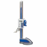
A height gauge is a precision measuring instrument used to determine vertical dimensions from a reference surface, usually a surface plate. To use one, first, ensure both the height gauge and the workpiece are clean and on a stable, flat surface plate. Zero the gauge by gently lowering the scriber or probe until it just touches the surface plate, then lock the main scale or digital display. For a direct measurement, raise the scriber until it touches the top surface of the workpiece, then read the measurement from the scale or display. For differential measurements, set the gauge to a known height, then measure the difference between that height and the workpiece. When using a scriber, you can lightly scribe a line on the workpiece at the desired height. Always ensure the scriber is perpendicular to the surface being measured for accuracy.

What is the purpose of a surface roughness tester?

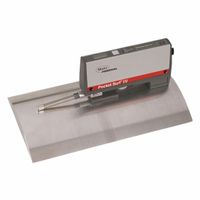
A surface roughness tester, also known as a profilometer or roughometer, is a precision instrument used to measure the texture or topography of a surface. Its primary purpose is to quantify the irregularities present on a material's surface, which are critical for understanding and controlling various aspects of product quality and performance. These devices work by dragging a stylus (a small, sharp probe) across the surface, recording the vertical displacement as it encounters peaks and valleys. Alternatively, non-contact methods using optical sensors or lasers can also be employed. The data collected is then used to calculate various roughness parameters, such as Ra (average roughness), Rz (maximum peak-to-valley height), and Rq (root mean square roughness), among others. The applications of surface roughness testers are widespread across industries. In manufacturing, they are essential for ensuring that machined parts meet specified tolerances, as surface finish directly impacts friction, wear, lubrication, and fatigue life. For example, in automotive, aerospace, and medical device manufacturing, precise surface finishes are crucial for component functionality and longevity. In the coatings industry, roughness measurements help determine adhesion properties and appearance. Additionally, they are used in research and development to characterize new materials and optimize manufacturing processes. By providing quantitative data on surface characteristics, these testers enable quality control, process improvement, and ultimately, the production of higher-performing and more reliable products.

How do you read a vernier caliper?

To read a vernier caliper, follow these steps:1. **Identify the main scale reading:** This is the last full millimeter or inch mark visible on the main scale to the left of the zero mark on the vernier scale. 2. **Identify the vernier scale reading:** Find the mark on the vernier scale that perfectly aligns with any mark on the main scale. The number of this aligned mark on the vernier scale, multiplied by the least count of the vernier caliper (usually 0.02 mm, 0.05 mm, or 0.001 inches), gives the fractional part of the measurement. 3. **Calculate the total reading:** Add the main scale reading and the vernier scale reading.For example, if the main scale reading is 25 mm and the 7th mark on the vernier scale aligns with a main scale mark, and the least count is 0.02 mm, then the vernier scale reading is 7 * 0.02 mm = 0.14 mm. The total reading would be 25 mm + 0.14 mm = 25.14 mm.

What are the applications of thickness gauges?

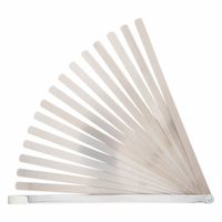
Thickness gauges have a wide range of applications across various industries, primarily for quality control, material verification, and safety. In manufacturing, they are crucial for ensuring uniform thickness in products like plastic films, metal sheets, and coatings, which directly impacts product performance and lifespan. For example, in the automotive industry, they are used to measure paint thickness to ensure adequate corrosion protection and a consistent finish. In the construction sector, thickness gauges are employed to assess the integrity of structures, such as the thickness of concrete slabs or steel beams, to ensure they meet safety standards. They are also vital in the aerospace industry for checking the thickness of aircraft components, where even minor deviations can have significant safety implications. Furthermore, thickness gauges are used in maintenance and inspection for pipeline integrity, ensuring that pipes carrying liquids or gases are not corroded or worn down to an unsafe level. They are also applied in the packaging industry to verify the thickness of materials like foils and cartons, affecting both product protection and cost efficiency. Different types of thickness gauges, such as ultrasonic, magnetic, and eddy current, are used depending on the material and application requirements.

How do you maintain precision measuring tools?

Maintaining precision measuring tools is crucial for ensuring accuracy and extending their lifespan. Here are key practices:1. Cleanliness: Always clean tools before and after use. Dust, oil, and grime can affect readings and cause wear. Use a lint-free cloth and appropriate cleaning solutions; for example, isopropyl alcohol can be used for metal surfaces. Avoid harsh chemicals that could damage the tool's finish or calibration. 2. Proper Storage: Store tools in their original cases or protective containers when not in use. This prevents physical damage, exposure to dust, and temperature fluctuations. Store them in a dry, stable environment to avoid corrosion and material expansion/contraction. 3. Handling with Care: Precision tools are delicate. Avoid dropping them or subjecting them to impacts. Do not force adjustments or overtighten clamps, as this can lead to deformation and loss of accuracy. 4. Calibration and Verification: Regularly calibrate tools against known standards. For example, micrometers and calipers should be checked for zero error. The frequency of calibration depends on usage, manufacturer recommendations, and quality standards. Keep detailed records of calibration dates and results. 5. Lubrication: Apply a thin layer of light machine oil to moving parts of tools like micrometers or calipers to ensure smooth operation and prevent rust. Avoid excessive lubrication, as it can attract dust. 6. Temperature Control: Use and store tools at a stable temperature, ideally around 20°C (68°F), as significant temperature changes can cause material expansion or contraction, affecting precision. 7. Training: Ensure that all users are properly trained on the correct use and maintenance of the tools. Improper handling is a common cause of damage and inaccurate measurements.

What is the accuracy of a digital caliper?

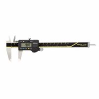
Digital calipers are precise measuring instruments commonly used in various industries for accurate measurements. Their accuracy is generally high, typically ranging from ±0.01 mm to ±0.03 mm (or ±0.0005 inches to ±0.001 inches), depending on the specific model and quality of the caliper. This high level of precision makes them suitable for tasks requiring tight tolerances. Factors influencing their accuracy include the quality of the manufacturing, the calibration of the instrument, and environmental conditions such as temperature fluctuations. Regular calibration and proper handling are crucial to maintain their accuracy over time.

How do you perform a pass/fail test with pin gauges?

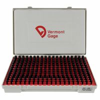
To perform a pass/fail test with pin gauges, you generally use a "go/no-go" approach. This involves two pin gauges: a "go" gauge, which represents the maximum acceptable size, and a "no-go" gauge, which represents the minimum acceptable size (or vice-versa, depending on whether you're checking an internal bore or an external feature). For an internal feature (like a hole):1. Take the "go" gauge. It should be slightly smaller than the nominal size of the hole, allowing it to pass through if the hole is within tolerance. Gently insert the "go" gauge into the hole. If it passes through without force, the "go" condition is met. 2. Take the "no-go" gauge. This gauge should be slightly larger than the nominal size of the hole. Attempt to insert the "no-go" gauge into the hole. If it does NOT enter the hole, then the "no-go" condition is met.If the "go" gauge passes and the "no-go" gauge does not pass, then the part is within tolerance and passes the test. If the "go" gauge does not pass, the hole is too small. If the "no-go" gauge passes, the hole is too large. For an external feature (like a shaft):1. Take the "go" gauge (which would be a ring gauge or a caliper set to the maximum acceptable dimension). The "go" gauge should easily slide over the shaft if it's within tolerance. 2. Take the "no-go" gauge (a ring gauge or caliper set to the minimum acceptable dimension). The "no-go" gauge should NOT slide over the shaft.If the "go" gauge fits and the "no-go" gauge does not fit, the shaft passes. Otherwise, it fails. The key is to use the gauges with minimal force to avoid deforming the part or the gauge, which could lead to inaccurate readings. Regularly cleaning and calibrating the pin gauges are also crucial for maintaining accuracy.