Call +(254) 703 030 000 / 751 483 999 / 721 704 777
.....Read More

Frequently Asked Questions
What are pin, plug, and ring gauges used for?
Pin, plug, and ring gauges are precision tools used in manufacturing and quality control to ensure the accuracy and consistency of dimensions in machined parts.
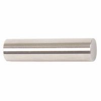
Pin gauges, also known as pin gages, are cylindrical rods used to measure the diameter of holes. They come in sets with incremental sizes, allowing users to check the fit and tolerance of holes by inserting the pins. They are essential for verifying hole sizes in components where precision is critical, such as in aerospace and automotive industries.
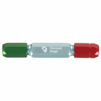
Plug gauges are similar to pin gauges but are typically larger and used for checking the size and roundness of holes. They consist of a handle with a cylindrical end that fits into the hole being measured. Plug gauges can be single-ended or double-ended, with "go" and "no-go" ends to quickly determine if a hole is within specified tolerances. They are widely used in quality control processes to ensure that parts meet design specifications.
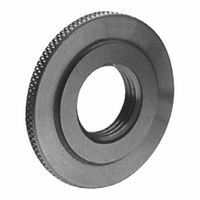
Ring gauges are used to measure the external diameters of cylindrical objects, such as shafts. They are circular tools with a precisely machined internal diameter. Like plug gauges, ring gauges can also be "go" and "no-go" types, allowing for quick assessment of whether a part's diameter is within acceptable limits. They are crucial in industries where the fit between mating parts is vital, such as in mechanical assemblies and bearing manufacturing.
Together, these gauges help maintain high standards of precision and quality in manufacturing processes, ensuring that parts fit together correctly and function as intended. They are indispensable in environments where dimensional accuracy is paramount.
How do Go/No-Go gauges work?
Go/No-Go gauges are precision tools used to check the dimensional tolerances of manufactured parts. They ensure that parts meet specified limits without requiring detailed measurements. These gauges come in two types: plug gauges for internal dimensions and ring or snap gauges for external dimensions.
A Go/No-Go gauge consists of two ends or sections: the "Go" end and the "No-Go" end. The "Go" end is designed to fit within or over the part if it is within the acceptable tolerance range. If the "Go" end fits, the part is considered to be at least at the minimum acceptable dimension. Conversely, the "No-Go" end should not fit if the part is within tolerance. If the "No-Go" end fits, the part exceeds the maximum allowable dimension and is considered out of tolerance.
For plug gauges, the "Go" end is slightly smaller than the minimum acceptable dimension, while the "No-Go" end is slightly larger than the maximum acceptable dimension. For ring or snap gauges, the "Go" end is slightly larger than the minimum acceptable dimension, and the "No-Go" end is slightly smaller than the maximum acceptable dimension.
These gauges are used in quality control processes to quickly and efficiently verify that parts are manufactured within specified limits. They are particularly useful in high-volume production environments where speed and accuracy are critical. By using Go/No-Go gauges, manufacturers can ensure consistency and reliability in their products, reducing the risk of defects and ensuring compliance with design specifications.
What is the difference between plain and threaded plug gauges?
Plain plug gauges and threaded plug gauges are both used to measure the dimensions of holes, but they serve different purposes and are designed differently.
Plain Plug Gauges:
- Purpose: Used to measure the diameter of smooth, cylindrical holes.
- Design: Consist of a simple cylindrical shape without any threads. They typically have two ends: a "Go" end and a "No-Go" end. The "Go" end should fit into the hole, while the "No-Go" end should not, ensuring the hole is within specified tolerances.
- Application: Commonly used in quality control to verify the diameter of drilled or reamed holes in manufacturing processes.
- Material: Usually made from hardened steel or carbide for durability and precision.
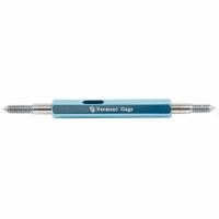
Threaded Plug Gauges:
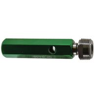
- Purpose: Used to measure the accuracy of internal threads in a hole.
- Design: Feature threads that match the specifications of the internal threads they are meant to measure. Like plain plug gauges, they also have "Go" and "No-Go" ends.
- Application: Essential in industries where threaded components are used, ensuring that the internal threads of a hole are correctly sized and can accommodate the corresponding external threads.
- Material: Also made from hardened steel or carbide, but with precise threading to match specific thread standards.
In summary, the primary difference lies in their design and application: plain plug gauges are for smooth holes, while threaded plug gauges are for threaded holes. Both types ensure that components meet specified tolerances, but they are used in different contexts depending on whether the hole is threaded or not.
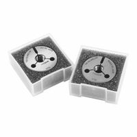
How are threaded ring gauges used?
Threaded ring gauges are precision tools used to measure the external threads of screws, bolts, and other threaded components. They ensure that these components meet specific dimensional and tolerance requirements. The gauges come in two main types: Go and No-Go.
1. **Go Ring Gauge**: This gauge checks the minimum material condition. It should easily pass over the entire length of the thread without force. If the component fits the Go gauge, it indicates that the thread's major diameter, pitch diameter, and minor diameter are within the lower tolerance limits.
2. **No-Go Ring Gauge**: This gauge checks the maximum material condition. It should not pass over the thread more than two turns. If the component does not fit the No-Go gauge, it confirms that the thread's dimensions do not exceed the upper tolerance limits.
**Usage Process**:
- **Preparation**: Ensure the gauge and the component are clean and free from debris. This prevents inaccurate readings.
- **Inspection**: Start with the Go gauge. Slide it over the threaded component. If it fits smoothly, proceed to the No-Go gauge.
- **Verification**: Attempt to fit the No-Go gauge. It should not pass more than two turns. If it does, the component is out of tolerance.
- **Documentation**: Record the results for quality control and compliance purposes.
Threaded ring gauges are essential in manufacturing and quality assurance processes, ensuring that threaded components fit correctly and function as intended in their applications. They help prevent assembly issues, leaks, and mechanical failures by verifying thread accuracy and consistency.
What are the types of gauges used for tapered pipe-threaded products?
The types of gauges used for tapered pipe-threaded products include:
1. **Plug Gauges**: Used to check the internal threads of a pipe. They ensure that the internal threads are correctly sized and tapered. Plug gauges come in two types: Go and No-Go. The Go gauge should fit into the pipe, while the No-Go gauge should not, ensuring the threads are within tolerance.
2. **Ring Gauges**: Used to check the external threads of a pipe. Similar to plug gauges, they also come in Go and No-Go types. The Go ring gauge should fit over the external threads, while the No-Go gauge should not, confirming the external threads are correctly sized and tapered.
3. **Caliper Gauges**: These are used for measuring the pitch diameter of the threads. They help in verifying the accuracy of the thread pitch and ensure that the threads are not too tight or too loose.
4. **Thread Depth Gauges**: Used to measure the depth of the threads in a pipe. This ensures that the threads are cut to the correct depth, which is crucial for ensuring a proper seal when the pipes are joined.
5. **Taper Gauges**: These are used to measure the taper of the threads. They ensure that the taper angle is correct, which is essential for the proper fit and sealing of the pipe threads.
6. **Profile Projectors**: Although not a gauge in the traditional sense, profile projectors can be used to visually inspect the thread profile and ensure it matches the required specifications.
These gauges are essential for ensuring the quality and functionality of tapered pipe-threaded products, as they verify that the threads meet the necessary standards and specifications.
How do you determine if a part is within tolerance using gauges?
To determine if a part is within tolerance using gauges, follow these steps:
1. **Identify Tolerance Specifications**: Obtain the engineering drawing or specification sheet for the part, which details the acceptable tolerance range for each dimension.
2. **Select the Appropriate Gauge**: Choose the correct type of gauge based on the dimension and tolerance to be measured. Common gauges include calipers, micrometers, dial indicators, and go/no-go gauges.
3. **Calibrate the Gauge**: Ensure the gauge is calibrated according to the manufacturer's instructions. Calibration should be done regularly to maintain accuracy.
4. **Clean the Part and Gauge**: Remove any debris, oil, or dirt from both the part and the gauge to prevent measurement errors.
5. **Measure the Part**: Use the gauge to measure the specific dimension of the part. For go/no-go gauges, attempt to fit the "go" side and ensure the "no-go" side does not fit. For other gauges, read the measurement directly.
6. **Compare to Tolerance Range**: Compare the measured value to the specified tolerance range. If using a go/no-go gauge, the part is within tolerance if the "go" side fits and the "no-go" side does not.
7. **Record the Measurement**: Document the measurement and the result (within or out of tolerance) for quality control records.
8. **Decision Making**: If the part is within tolerance, it can proceed to the next stage of production or assembly. If it is out of tolerance, it may require rework, rejection, or further inspection.
9. **Repeat as Necessary**: For batch production, repeat the process for a statistically significant sample size to ensure overall quality.
By following these steps, you can accurately determine if a part is within the specified tolerance using gauges.
What is the purpose of L-1, L-2, L-3, and 6-step gauges?
L-1, L-2, L-3, and 6-step gauges are precision tools used in the manufacturing and quality control of threaded components, particularly in the context of ensuring the accuracy and consistency of screw threads.
1. **L-1 Gauge**: The L-1 gauge is primarily used to check the basic pitch diameter of a threaded part. It ensures that the thread is within the specified tolerance range for the pitch diameter, which is crucial for the proper fit and function of the threaded connection. The L-1 gauge is often the first gauge used in the inspection process.
2. **L-2 Gauge**: The L-2 gauge is used to inspect the effective diameter of the thread beyond the basic pitch diameter. It provides a more comprehensive check by ensuring that the thread's functional diameter is within acceptable limits. This gauge is typically used for more critical applications where additional precision is required.
3. **L-3 Gauge**: The L-3 gauge is employed to verify the minor diameter of internal threads. It ensures that the internal thread's minor diameter is not too small, which could affect the assembly and strength of the threaded connection. This gauge is essential for ensuring that the internal threads can accommodate the mating external threads without interference.
4. **6-Step Gauge**: The 6-step gauge is a comprehensive tool that combines multiple checks into a single gauge. It is used to inspect various thread parameters, including pitch diameter, major diameter, minor diameter, and thread form. This gauge provides a thorough assessment of the thread's overall quality and compliance with specifications.
These gauges are critical in maintaining the integrity and reliability of threaded connections in various industries, including automotive, aerospace, and manufacturing, where precision and safety are paramount.