Call +(254) 703 030 000 / 751 483 999 / 721 704 777
.....Read More


Frequently Asked Questions
What are quick-check reference gauges used for?
Quick-check reference gauges are used for the rapid and efficient verification of measurement tools and equipment in various industrial and manufacturing settings. These gauges serve as a benchmark to ensure that instruments such as calipers, micrometers, and other precision measurement devices are providing accurate readings. By using quick-check reference gauges, operators can quickly determine if their measurement tools are within acceptable tolerance levels without the need for extensive calibration processes.
The primary purpose of these gauges is to maintain quality control and ensure consistency in production processes. They help in identifying any deviations or inaccuracies in measurement tools that could lead to defects or non-conformities in the final product. This is particularly crucial in industries where precision is critical, such as aerospace, automotive, and electronics manufacturing.
Quick-check reference gauges are typically designed to be user-friendly, allowing for swift checks that minimize downtime in production. They are often made from durable materials to withstand frequent use and are calibrated to national or international standards to ensure reliability.
In addition to their use in quality control, these gauges can also be employed in training scenarios to help new operators understand the importance of accurate measurements and how to verify their tools effectively. By incorporating quick-check reference gauges into regular maintenance routines, companies can enhance their overall operational efficiency, reduce waste, and improve product quality.
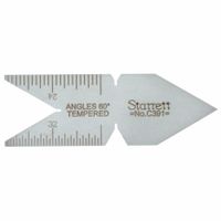
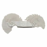
How do you use a center gauge?
A center gauge, also known as a fishtail gauge, is primarily used in metalworking to set and check the angles of lathe cutting tools and to align the threading tool on a lathe. Here’s how to use it:
1. **Tool Angle Verification**:
- Place the center gauge against the cutting tool. The gauge has various angles cut into it, typically 60 degrees for standard threads.
- Ensure the tool’s cutting edge aligns perfectly with the angle on the gauge. This ensures the tool is ground to the correct angle for threading.
2. **Thread Alignment**:
- Mount the threading tool in the lathe tool post.
- Position the center gauge between the threading tool and the workpiece.
- Adjust the tool post so that the threading tool aligns with the 60-degree angle on the gauge. This ensures the tool is perpendicular to the workpiece, crucial for accurate thread cutting.
3. **Checking Thread Pitch**:
- Some center gauges have scales for checking thread pitch. Align the gauge’s scale with the threads on a screw or bolt to verify the pitch.
4. **Tool Height Adjustment**:
- Use the center gauge to ensure the tool is at the correct height relative to the workpiece centerline. This is done by aligning the gauge’s flat edge with the lathe center.
5. **Verification**:
- After setting, perform a test cut and use the gauge to verify the thread profile matches the desired specification.
By using a center gauge, machinists ensure precision in tool setup, leading to accurate and consistent threading operations.
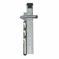
What is the purpose of a drill point angle gauge?
A drill point angle gauge is a precision tool used to measure and verify the angle of the point on a drill bit. Its primary purpose is to ensure that the drill bit has the correct point angle for the material being drilled, which is crucial for efficient drilling performance and longevity of the drill bit. The gauge helps in maintaining consistency and accuracy in the sharpening process of drill bits.
Different materials require different drill point angles for optimal drilling. For instance, a standard drill bit for general-purpose use typically has a point angle of 118 degrees, which is suitable for drilling into soft materials like wood and some plastics. Harder materials, such as metals, often require a sharper angle, like 135 degrees, to reduce the amount of force needed and to prevent the bit from wandering.
Using a drill point angle gauge, machinists and technicians can quickly check the angle of a drill bit before use or after sharpening. This ensures that the bit will perform as expected, reducing the risk of breakage, improving the quality of the hole, and extending the life of the drill bit. The gauge typically features a protractor-like design with markings for common angles, allowing for easy and accurate measurement.
In summary, the drill point angle gauge is an essential tool in any workshop or manufacturing setting where precision drilling is required. It aids in maintaining the correct geometry of drill bits, ensuring efficient and effective drilling operations across various materials.
How do you measure a radius with a radius gauge?
To measure a radius with a radius gauge, follow these steps:
1. **Select the Appropriate Gauge**: Choose a radius gauge set that covers the range of radii you need to measure. These sets typically include multiple blades, each with a different radius.
2. **Identify the Radius to Measure**: Determine the approximate size of the radius you need to measure. This can be done by visual estimation or using a ruler for a rough measurement.
3. **Choose the Correct Blade**: From the gauge set, select the blade that closely matches the estimated radius. Each blade is marked with its specific radius size.
4. **Position the Gauge**: Place the selected blade against the curved surface of the object. Ensure that the blade fits snugly along the curve without any gaps or overlaps.
5. **Check for Fit**: Observe the contact between the blade and the surface. A perfect fit means the blade matches the radius of the curve. If there are gaps, try a different blade with a slightly larger or smaller radius until you find the best fit.
6. **Verify the Measurement**: Once the correct blade is found, double-check the fit by moving the gauge slightly along the curve to ensure consistent contact. The radius marked on the blade is the radius of the curve.
7. **Record the Measurement**: Note down the radius size indicated on the blade for documentation or further use.
8. **Repeat if Necessary**: If measuring multiple radii, repeat the process with different blades as needed.
Using a radius gauge provides a quick and accurate way to measure the radius of a curve, especially in manufacturing and quality control processes.
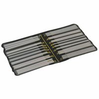
How do thread pitch gauges work?
Thread pitch gauges are tools used to measure the pitch or lead of a screw thread. They consist of a set of blades, each with teeth of a specific pitch. To use a thread pitch gauge, you follow these steps:
1. **Select the Gauge**: Choose a thread pitch gauge set that matches the type of thread you are measuring, either metric or imperial.
2. **Identify the Thread Type**: Determine whether the thread is internal (like a nut) or external (like a bolt).
3. **Match the Blade**: For external threads, place the gauge's teeth against the threads of the bolt or screw. For internal threads, insert the gauge into the nut or hole.
4. **Check the Fit**: Slide different blades into the threads until you find one that fits snugly without any gaps. The correct blade will sit perfectly in the grooves of the thread.
5. **Read the Measurement**: Once the correct blade is found, read the pitch value marked on the blade. This value represents the distance between threads, typically measured in millimeters for metric threads or threads per inch (TPI) for imperial threads.
6. **Verify the Measurement**: To ensure accuracy, check the fit of the gauge on multiple sections of the thread.
Thread pitch gauges are essential for identifying thread specifications, ensuring compatibility between threaded components, and preventing cross-threading. They are widely used in manufacturing, engineering, and maintenance applications.
What is the difference between a wire gauge and a sheet metal thickness gauge?
A wire gauge and a sheet metal thickness gauge are both tools used to measure thickness, but they apply to different materials and have distinct systems.
A wire gauge measures the diameter of a wire. It is used primarily in electrical and jewelry applications to determine the thickness of metal wires. The most common systems are the American Wire Gauge (AWG) and the Standard Wire Gauge (SWG). In these systems, a smaller gauge number indicates a thicker wire. For example, in AWG, a 10-gauge wire is thicker than a 20-gauge wire. The gauge number is inversely related to the wire's diameter.
On the other hand, a sheet metal thickness gauge measures the thickness of sheet metal. It is used in industries like automotive, construction, and manufacturing. The most common systems are the Manufacturers' Standard Gauge (MSG) and the Birmingham Gauge (BG). Unlike wire gauges, the relationship between gauge number and thickness can vary depending on the material (e.g., steel, aluminum). Generally, a lower gauge number indicates a thicker sheet, but the actual thickness can differ between materials. For instance, a 10-gauge steel sheet is thicker than a 20-gauge steel sheet, but the thickness in inches or millimeters can vary for the same gauge number across different materials.
In summary, while both gauges measure thickness, wire gauges are for wires and have a consistent inverse relationship between gauge number and diameter, whereas sheet metal gauges are for sheet metals and can vary in thickness for the same gauge number depending on the material.
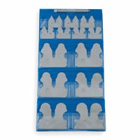
How do you use a tap, drill, and screw checker gauge?
To use a tap, drill, and screw checker gauge, follow these steps:
1. **Identify the Screw Size**: Place the screw into the corresponding hole on the screw checker gauge. The correct hole will allow the screw to fit snugly without excessive play. This determines the screw's diameter and thread pitch.
2. **Select the Drill Bit**: Once the screw size is identified, use the gauge to find the recommended drill bit size for creating a pilot hole. The gauge typically lists the appropriate drill bit size next to the screw size. This ensures the hole is neither too tight nor too loose for the screw.
3. **Drill the Pilot Hole**: Use the selected drill bit to create a pilot hole in the material. Ensure the hole is straight and clean to facilitate easy tapping and screwing.
4. **Choose the Tap**: If threading is required, select a tap that matches the screw size and thread pitch identified earlier. The gauge often provides this information, ensuring compatibility between the tap and screw.
5. **Tap the Hole**: Insert the tap into the drilled hole and turn it slowly, applying even pressure. Use a tap wrench for better control. Periodically reverse the tap to clear debris and prevent binding. Continue until the hole is fully threaded.
6. **Check the Threads**: Use the screw checker gauge to verify the threads by inserting the tapped hole into the corresponding gauge hole. This ensures the threads are correctly formed and will accommodate the screw.
7. **Insert the Screw**: Finally, insert the screw into the tapped hole. It should fit smoothly, indicating that the tap, drill, and screw checker gauge were used correctly.
This process ensures precision in creating threaded holes and selecting compatible screws, enhancing the quality and durability of the assembly.