Call +(254) 703 030 000 / 751 483 999 / 721 704 777
Showing 0 products
Frequently Asked Questions
What is the difference between turning and boring?
Turning and boring are both machining processes that remove material from a workpiece, primarily used for creating cylindrical shapes. However, they differ significantly in their operation and the features they produce.
Turning is performed on a lathe, where the workpiece rotates and a single-point cutting tool moves linearly along its axis. This process is used to reduce the diameter of the workpiece, creating external cylindrical surfaces, tapers, grooves, or threads. The tool approaches the rotating workpiece from the outside, gradually shaping its exterior.
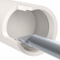
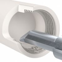
Boring, conversely, is an internal machining operation used to enlarge or refine an existing hole in a workpiece. While it can also be performed on a lathe, it often utilizes specialized boring machines. In boring, the cutting tool is typically mounted on a boring bar that extends into the pre-drilled or cast hole. The tool rotates or the workpiece rotates (depending on the machine), and the tool moves to remove material from the inner surface of the hole, creating a precise internal diameter.
In essence, turning shapes the outside of a part, while boring shapes the inside. Both are crucial for producing precise cylindrical components in manufacturing.
How do you choose the right boring bar for a job?
Choosing the right boring bar involves considering several factors to ensure optimal performance and accuracy. First, assess the workpiece material and its machinability. This influences the insert grade and geometry. Next, consider the bore diameter and depth; this dictates the bar's diameter and length. A larger diameter bar offers greater rigidity, crucial for minimizing vibration and achieving good surface finish, especially for deeper bores.
The type of boring operation (roughing, semi-finishing, or finishing) also plays a role. Roughing bars prioritize material removal, while finishing bars focus on precision and surface quality. Look at the machine's capabilities, including spindle speed, power, and tool holding.
Finally, evaluate the bar's damping characteristics. For long overhangs or unstable setups, a dampened boring bar can significantly reduce vibration and improve performance. Consider features like internal coolant delivery for chip evacuation and thermal stability.
What are the best practices for grooving operations?
Please specify the topic you would like me to elaborate on.
How do you prevent chatter in boring operations?
Chatter in boring operations is a self-excited vibration that can lead to poor surface finish, reduced tool life, and dimensional inaccuracies. Preventing chatter is crucial for efficient and high-quality machining.
Several strategies can be employed to mitigate chatter:1. Optimize Cutting Parameters: Adjusting cutting speed, feed rate, and depth of cut can significantly impact chatter. Generally, increasing cutting speed or decreasing the depth of cut can reduce chatter, but the optimal parameters are highly dependent on the material and tooling.
2. Increase System Rigidity: A stiffer machine-tool-workpiece system is less prone to vibrations. This can be achieved by:
* Using shorter and larger diameter boring bars.
* Employing tool holders with higher stiffness (e.g., hydraulic or shrink-fit holders).
* Ensuring rigid fixturing of the workpiece.
* Using machines with higher static and dynamic stiffness.
3. Damping: Incorporating damping mechanisms can absorb vibration energy. This includes:
* Using boring bars with integrated damping features (e.g., tuned mass dampers).
* Applying viscoelastic materials to dampen vibrations.
4. Tool Geometry: The design of the cutting tool can influence chatter.
* Using tools with a positive rake angle can reduce cutting forces and thus chatter.
* Varying the helix angle or using unequal pitch inserts on multi-insert tools can break up the regenerative feedback loop that causes chatter.
* Smaller nose radii can sometimes reduce chatter, but this can affect surface finish.
5. Coolant Application: Proper coolant application can lubricate the cutting zone, reduce friction, and dissipate heat, all of which can indirectly help in chatter prevention.
6. Process Planning:
* Taking multiple passes with smaller depths of cut rather than one deep cut.
* Avoiding resonant frequencies of the machine-tool system.By carefully considering and implementing these strategies, operators can significantly reduce or eliminate chatter in boring operations, leading to improved part quality and increased productivity.
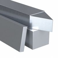
What materials are commonly used for lathe tool bits?
Lathe tool bits are crucial for shaping materials on a lathe. Their effectiveness depends on the material they're made from, which must withstand high temperatures, friction, and pressure. Common materials include:
High-Speed Steel (HSS): This is a popular and economical choice for general machining. HSS bits maintain their hardness at temperatures up to 600°C, making them suitable for softer materials and intermittent cutting. They are easy to sharpen and resharpen.
Carbide (Cemented Carbide): Composed of tungsten carbide particles bonded in a cobalt matrix, carbide bits are significantly harder and more heat-resistant than HSS, performing well at temperatures up to 1000°C. They are ideal for machining hard materials and for high-speed cutting. Different grades exist, optimized for various applications.
Ceramics: Made from aluminum oxide or silicon nitride, ceramic tool bits offer extreme hardness and high heat resistance, suitable for very high-speed machining of hard alloys and cast iron. They are brittle and require rigid setups.
Cermets: A composite of ceramic and metallic materials (e.g., titanium carbonitride with a nickel-cobalt binder), cermets offer a balance of hardness, toughness, and wear resistance. They are often used for finishing operations on steel.
Cubic Boron Nitride (CBN): Next to diamond, CBN is one of the hardest known materials. It's used for machining hardened steels, superalloys, and cast irons at high temperatures. CBN inserts are typically brazed onto carbide shanks.
Polycrystalline Diamond (PCD): PCD is synthetic diamond material bonded to a carbide substrate. It is exceptionally hard and wear-resistant, making it ideal for machining non-ferrous materials like aluminum, copper, and composites, and for high-precision finishing. It cannot be used on ferrous metals due to a chemical reaction with iron at high temperatures.
How do you calculate the correct cutting speed for turning?
To calculate the correct cutting speed (Vc) for turning, you typically use the following formula:
Vc = (π * D * n) / 1000
Where: * Vc = Cutting speed in meters per minute (m/min)
* π (pi) ≈ 3.14159
* D = Diameter of the workpiece in millimeters (mm)
* n = Spindle rotational speed in revolutions per minute (rpm)This formula helps determine the speed at which the cutting edge of the tool passes over the surface of the workpiece. The "1000" in the denominator is used to convert millimeters to meters.
However, selecting the "correct" cutting speed isn't just about calculation. It also involves several critical factors:1. **Material of the Workpiece:** Different materials (e.g., steel, aluminum, plastics) have varying machinability, requiring different cutting speeds. Harder materials generally require lower cutting speeds.
2. **Tool Material:** The type of cutting tool material (e.g., high-speed steel, carbide, ceramic) significantly impacts the recommended cutting speed. Carbide tools can typically withstand much higher speeds than HSS tools.
3. **Depth of Cut and Feed Rate:** These parameters influence the forces on the tool and the amount of material being removed per revolution, affecting the optimal cutting speed.
4. **Machine Rigidity and Power:** The machine's stability and available power limit the maximum feasible cutting speed and feed.
5. **Surface Finish Requirements:** Higher cutting speeds can sometimes lead to better surface finishes, but too high can cause vibrations and poor finish.
6. **Coolant/Lubrication:** The use and type of coolant can influence the permissible cutting speed by reducing heat and friction.
7. **Tool Wear and Life:** The goal is often to balance high productivity with acceptable tool life. Higher cutting speeds can lead to faster tool wear.Manufacturers of cutting tools provide recommended cutting speed ranges for various workpiece materials and tool combinations. It's often best to start with these recommendations and adjust based on observations of tool wear, chip formation, surface finish, and machine performance.
What are the advantages of using carbide inserts in turning operations?
Carbide inserts offer several advantages in turning operations, primarily due to their superior hardness, wear resistance, and high-temperature strength compared to traditional high-speed steel tools. These properties allow for significantly higher cutting speeds and feed rates, leading to increased productivity and reduced machining time. The excellent wear resistance of carbide inserts translates to longer tool life, minimizing downtime for tool changes and lowering overall tooling costs. Their ability to maintain sharpness at elevated temperatures, generated during high-speed cutting, ensures consistent surface finish and dimensional accuracy of the workpiece. Furthermore, carbide inserts are suitable for machining a wide range of materials, including hardened steels, cast iron, and superalloys, which are challenging for other tool materials. The variety of geometries and coatings available for carbide inserts also allows for optimized performance in specific applications, enhancing chip control and reducing cutting forces.
How do you set up a lathe for internal threading?
To set up a lathe for internal threading, begin by ensuring the workpiece is securely chucked and runs true. Select the correct threading tool for the desired pitch and thread form, ensuring it has adequate clearance. Mount the tool in the tool post, setting it precisely on the centerline of the workpiece. Next, set the lathe's gearbox and lead screw to the correct pitch for the thread. This involves consulting the threading chart on your machine. Carefully position the threading tool so that its tip is just touching the bore's starting point, then zero out your compound slide and cross slide dials. Engage the half-nuts to initiate the threading pass, allowing the tool to cut a shallow groove. For subsequent passes, use the compound slide to feed the tool into the material, typically at an angle matching half of the thread angle (e.g., 29 or 30 degrees for a 60-degree thread). This ensures that only one side of the tool is cutting during each pass, which helps produce a cleaner thread and reduces tool wear. Continuously apply cutting fluid to dissipate heat and lubricate the cutting action. Monitor the thread quality and periodically check the thread with a thread gauge to ensure accuracy. Repeat passes, incrementally advancing the compound slide, until the desired thread depth is achieved. Back the tool out at the end of each pass, reverse the spindle, and return the carriage to the starting position for the next cut.
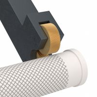
What is the purpose of knurling in machining?
Knurling is a manufacturing process that creates a pattern of straight, angled, or crossed lines on a material, most commonly metal. The primary purpose of knurling in machining is to provide a gripping surface for parts that need to be turned or held by hand. This improves the user's ability to grip the object, especially if their hands are wet, oily, or gloved, preventing slippage and ensuring secure handling.
Beyond enhanced grip, knurling also serves several other important functions: * **Aesthetic appeal:** Knurled patterns can add a decorative element to a part, improving its visual appearance.
* **Assembly:** Knurling can create an interference fit between two mating parts, such as a metal insert pressed into a plastic component. The raised ridges of the knurl bite into the softer material, creating a strong, secure connection without the need for threads or adhesives.
* **Repair and restoration:** In some cases, knurling can be used to slightly expand the diameter of a worn shaft or hole, allowing it to fit more snugly into a mating part and extending the lifespan of components.
* **Increased surface area:** The textured surface created by knurling slightly increases the overall surface area of a part, which can be beneficial for heat dissipation in certain applications, though this is a less common primary purpose.Overall, knurling is a versatile and valuable process in machining, offering both functional and aesthetic benefits to manufactured parts.
How do you maintain and sharpen lathe tools?
Maintaining and sharpening lathe tools is crucial for optimal performance and longevity. Regular cleaning after each use prevents the buildup of chips and debris, which can hinder cutting efficiency. Inspect tools for wear, chips, or cracks before and after use.
Sharpening involves using abrasive tools like grinding wheels or diamond hones. The goal is to restore the original cutting angles and create a sharp edge. For high-speed steel (HSS) tools, a bench grinder is commonly used. Ensure a steady hand and consistent pressure to avoid overheating the tool, which can alter its temper. Carbide-tipped tools often require diamond wheels due to their hardness.
Proper sharpening techniques include maintaining the correct relief angles and rake angles specific to the type of tool and material being cut. A tool rest is essential for stability and safety during grinding. After grinding, a finer grit stone or honing guide can be used to achieve an even sharper edge.
Storage is also important. Keep tools organized in a protective case or rack to prevent damage and corrosion. Oiling tools, especially those made of carbon steel, can help prevent rust.