Call +(254) 703 030 000 / 751 483 999 / 721 704 777
- Home
- Power Transmission
- Shaft Couplings Universal Joints
.....Read More
Frequently Asked Questions
What are the different types of shaft couplings?
Shaft couplings are mechanical devices used to connect two shafts together for the purpose of transmitting power. They can accommodate misalignment, absorb shock, and reduce vibration. The main types of shaft couplings include:
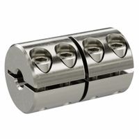
1. **Rigid Couplings**: These are used when precise shaft alignment is required. They do not allow for any misalignment and are typically used in applications where shafts are already aligned. Types include sleeve or muff couplings, clamp or split-muff couplings, and flange couplings.
2. **Flexible Couplings**: These accommodate misalignment and are used to absorb shock and vibration. They are suitable for applications where some degree of misalignment is unavoidable. Types include:
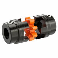
- **Jaw Couplings**: Consist of two hubs and an elastomeric element, known as a spider, which provides flexibility.
- **Oldham Couplings**: Consist of three discs, with the middle disc floating between the two outer discs, allowing for parallel misalignment.
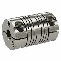
- **Beam Couplings**: Made from a single piece of material with spiral cuts, allowing for flexibility in all directions.
- **Diaphragm Couplings**: Use a thin, flexible metal diaphragm to transmit torque while accommodating misalignment.
- **Disc Couplings**: Use a series of thin, flexible metal discs to transmit torque and accommodate misalignment.
3. **Fluid Couplings**: Use a hydraulic fluid to transmit torque between shafts. They are used in applications requiring smooth acceleration and torque control, such as in automotive and industrial machinery.
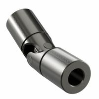
4. **Universal Joints**: Allow for angular misalignment between shafts. They are commonly used in applications like drive shafts in vehicles.
5. **Magnetic Couplings**: Use magnetic forces to transmit torque without physical contact, ideal for applications requiring hermetic sealing.
Each type of coupling has its own advantages and is selected based on the specific requirements of the application, such as torque capacity, misalignment accommodation, and environmental conditions.
How do flexible couplings work?
Flexible couplings are mechanical devices used to connect two rotating shafts, allowing for the transmission of torque while accommodating misalignment and reducing the transmission of shock loads. They work by providing a flexible connection between the shafts, which can compensate for various types of misalignment, including angular, parallel, and axial misalignments.
The basic principle of flexible couplings involves the use of flexible elements or mechanisms that can absorb and compensate for misalignments. These elements can be made from materials such as rubber, elastomers, or metal, depending on the specific design and application requirements. The flexibility of these elements allows the coupling to bend or stretch slightly, accommodating the misalignment between the connected shafts.
There are several types of flexible couplings, each with its own mechanism for providing flexibility:
1. **Elastomeric Couplings**: These use rubber or elastomeric materials to provide flexibility. The material deforms under load, allowing for misalignment compensation and vibration damping.
2. **Gear Couplings**: Consist of two hubs with external teeth that mesh with internal teeth on a sleeve. The gear teeth allow for slight movement, accommodating misalignment.
3. **Disc Couplings**: Use thin metal discs that flex to accommodate misalignment. The discs are arranged in a pack and connected to the hubs, allowing for angular and axial flexibility.
4. **Universal Joints**: Allow for large angular misalignments by using a cross-shaped pivot point that connects the two shafts.
5. **Oldham Couplings**: Consist of three discs, with the middle disc sliding between the other two, allowing for parallel misalignment.
By accommodating misalignment, flexible couplings help prevent excessive wear and tear on machinery, reduce noise and vibration, and improve the overall efficiency and lifespan of mechanical systems.
What is the purpose of a universal joint?
A universal joint, also known as a U-joint, is a mechanical device used to connect two rotating shafts that are not in a straight line. Its primary purpose is to transmit torque and rotary motion between these shafts, allowing for angular misalignment. This capability is crucial in applications where the shafts are not perfectly aligned or where they need to move relative to each other.
The universal joint consists of a pair of hinges located close together, oriented at 90 degrees to each other, connected by a cross shaft. This design allows the joint to flex in multiple directions, accommodating changes in angle between the connected shafts. As a result, it can handle the complex motion and varying angles that occur in many mechanical systems.
Universal joints are commonly used in automotive applications, such as in the drive shafts of rear-wheel-drive vehicles, where they connect the transmission to the differential. They are also found in various industrial machinery, aerospace applications, and marine equipment, where they facilitate the transfer of power in systems with misaligned or moving components.
By allowing for angular displacement, universal joints help reduce stress on the connected shafts and components, enhancing the durability and performance of the mechanical system. They also contribute to smoother operation by compensating for misalignment and reducing vibration. However, universal joints can introduce some speed variation in the driven shaft, known as "velocity fluctuation," which can be mitigated by using a double Cardan joint or constant velocity joint in applications requiring uniform speed.
How do you select the right shaft coupling for an application?
To select the right shaft coupling for an application, consider the following factors:
1. **Torque Requirements**: Determine the maximum torque the coupling must transmit. This ensures the coupling can handle the load without failure.
2. **Misalignment Tolerance**: Identify the types and degrees of misalignment (angular, parallel, axial) the coupling must accommodate. Choose a coupling that can handle the expected misalignment without excessive wear or loss of performance.
3. **Speed**: Consider the operational speed of the application. High-speed applications may require couplings with specific balance and vibration characteristics.
4. **Environmental Conditions**: Assess the operating environment, including temperature, humidity, chemical exposure, and presence of dust or debris. Select materials and designs that can withstand these conditions.
5. **Space Constraints**: Evaluate the available space for the coupling. Ensure the selected coupling fits within the spatial limitations while providing the necessary performance.
6. **Maintenance and Accessibility**: Consider the ease of installation, maintenance, and replacement. Some couplings require more frequent maintenance or are easier to install and replace than others.
7. **Cost**: Balance the cost of the coupling with its performance and longevity. While initial cost is important, consider the total cost of ownership, including maintenance and potential downtime.
8. **Application Type**: Different applications (e.g., pumps, conveyors, compressors) may have specific requirements. Choose a coupling designed for the specific application type.
9. **Material Compatibility**: Ensure the coupling materials are compatible with the shafts and any other connected components to prevent galvanic corrosion or other material-related issues.
10. **Industry Standards and Regulations**: Verify that the coupling meets any relevant industry standards or regulations for safety and performance.
By carefully evaluating these factors, you can select a shaft coupling that optimally meets the needs of your specific application.
What are the advantages of using precision motion control couplings?
Precision motion control couplings offer several advantages in various applications:
1. **Accuracy and Precision**: These couplings ensure high levels of accuracy and precision in motion control systems by minimizing backlash and maintaining alignment between connected components. This is crucial in applications requiring exact positioning, such as CNC machines and robotics.
2. **Vibration Damping**: Precision couplings can absorb and dampen vibrations, reducing wear and tear on machinery and improving the longevity and reliability of the system. This leads to smoother operation and less maintenance.
3. **Misalignment Compensation**: They can accommodate various types of misalignment (angular, parallel, and axial), which helps in maintaining system performance and reducing stress on components. This flexibility is essential in systems where perfect alignment is challenging to achieve.
4. **Torque Transmission**: These couplings efficiently transmit torque between components, ensuring that power is delivered effectively without loss. This is vital in high-performance applications where consistent torque is necessary.
5. **Compact Design**: Precision couplings often have a compact design, which is beneficial in space-constrained environments. This allows for more efficient use of space and integration into complex systems.
6. **Reduced Maintenance**: By minimizing wear and compensating for misalignment, precision couplings reduce the need for frequent maintenance, leading to lower operational costs and downtime.
7. **Versatility**: They are available in various materials and configurations, making them suitable for a wide range of applications, from industrial machinery to medical devices.
8. **Enhanced System Performance**: Overall, the use of precision motion control couplings enhances the performance of mechanical systems by ensuring smooth, accurate, and reliable operation, which is critical in high-precision environments.
How do rigid couplings differ from flexible couplings?
Rigid couplings and flexible couplings serve to connect two shafts in mechanical systems but differ significantly in design and application.
Rigid couplings are designed to connect two shafts so that they function as a single unit. They do not allow for any misalignment between the shafts. This type of coupling is ideal for applications where precise alignment is possible and necessary, such as in high-precision machinery. Rigid couplings are simple in design, often consisting of a single piece or two halves bolted together, and are typically used in applications where the shafts are already aligned and do not require any movement. They are known for their high torque transmission capability and are used in situations where maintaining alignment is critical.
Flexible couplings, on the other hand, are designed to accommodate misalignment between connected shafts. They can handle angular, parallel, and axial misalignments, as well as absorb shock loads and vibrations. This flexibility is achieved through various designs, such as elastomeric elements, gear teeth, or metallic discs, which allow for some movement between the shafts. Flexible couplings are used in applications where perfect alignment is difficult to achieve or maintain, such as in systems subject to thermal expansion, vibration, or where the shafts are mounted on separate supports. They help in reducing wear and tear on the connected equipment by compensating for misalignment and dampening vibrations.
In summary, the primary difference lies in their ability to handle misalignment: rigid couplings require precise alignment, while flexible couplings accommodate misalignment and provide additional benefits like vibration damping.
What are the common materials used for shaft couplings?
Common materials used for shaft couplings include:
1. **Steel**: Known for its strength and durability, steel is often used in heavy-duty applications. It can withstand high torque and is resistant to wear and tear.
2. **Stainless Steel**: Offers corrosion resistance along with strength, making it suitable for environments where rust and corrosion are concerns, such as in food processing or chemical industries.
3. **Aluminum**: Lightweight and corrosion-resistant, aluminum is used in applications where weight is a concern. It is not as strong as steel but is easier to machine and handle.
4. **Cast Iron**: Provides good strength and is cost-effective. It is commonly used in general-purpose applications but is heavier and more brittle than steel.
5. **Bronze**: Known for its good wear resistance and low friction properties, bronze is often used in couplings that require self-lubricating properties.
6. **Nylon and Other Plastics**: Used in applications where noise reduction and electrical insulation are important. They are lightweight and resistant to corrosion but have lower strength compared to metals.
7. **Rubber**: Often used in flexible couplings to absorb shock and vibration. Rubber can accommodate misalignment and is used in applications where noise reduction is important.
8. **Composite Materials**: These include carbon fiber and fiberglass, which offer high strength-to-weight ratios and are used in specialized applications requiring lightweight and high-performance materials.
Each material has its own set of properties that make it suitable for specific applications, depending on factors like load, speed, environmental conditions, and cost considerations.
How do you install a shaft coupling?
1. **Select the Right Coupling**: Choose a coupling that matches the shaft size, torque requirements, and application conditions.
2. **Inspect Components**: Check the coupling and shafts for any damage or debris. Ensure all components are clean and free from rust or burrs.
3. **Align Shafts**: Position the shafts to be as close to perfect alignment as possible. Use alignment tools like dial indicators or laser alignment systems for precision.
4. **Prepare Shafts**: Clean the shaft surfaces thoroughly. If necessary, apply a light coat of lubricant to ease installation.
5. **Install Coupling Hubs**: Slide the coupling hubs onto the shafts. If the fit is tight, gently heat the hubs to expand them slightly. Ensure the hubs are positioned correctly according to the manufacturer's specifications.
6. **Position Hubs**: Align the hubs so that the gap between them matches the coupling's specifications. Use a feeler gauge to check the gap.
7. **Secure Hubs**: Tighten the set screws or bolts to secure the hubs onto the shafts. Use a torque wrench to apply the correct torque as specified by the manufacturer.
8. **Install Coupling Element**: Attach the flexible element or spacer between the hubs, if applicable. Ensure it is seated properly and secured according to the coupling type.
9. **Check Alignment**: Recheck the alignment after installation. Adjust if necessary to ensure minimal misalignment.
10. **Tighten Fasteners**: Double-check all fasteners for proper tightness. Ensure all components are securely fastened.
11. **Test Run**: Start the machinery at low speed to observe the coupling's performance. Listen for unusual noises and check for vibrations.
12. **Final Inspection**: After a test run, inspect the coupling for any signs of wear or misalignment. Make adjustments if needed.
What are the signs of a failing shaft coupling?
Signs of a failing shaft coupling include:
1. **Vibration and Noise**: Increased vibration and unusual noises such as clanking or grinding can indicate misalignment or wear in the coupling.
2. **Excessive Wear**: Visible wear on the coupling components, such as cracks, corrosion, or deformation, suggests deterioration.
3. **Misalignment**: Misalignment between connected shafts can cause uneven wear and lead to coupling failure.
4. **Overheating**: Excessive heat generation around the coupling area can be a sign of friction due to misalignment or lack of lubrication.
5. **Lubrication Issues**: Leaking or insufficient lubrication can lead to increased friction and wear.
6. **Backlash**: Excessive play or backlash in the coupling can indicate wear or damage.
7. **Unusual Movement**: Lateral or axial movement beyond normal limits can suggest a failing coupling.
8. **Frequent Maintenance**: Increased frequency of maintenance or adjustments may indicate underlying issues with the coupling.
9. **Visual Damage**: Broken or missing components, such as bolts or keys, can be a clear sign of failure.
10. **Operational Inefficiency**: Reduced performance or efficiency in the connected machinery can be a result of coupling issues.
11. **Temperature Changes**: Unexplained temperature fluctuations in the coupling area can indicate problems.
12. **Alignment Marks**: Misalignment of previously aligned marks on the coupling can signal a shift or failure.
13. **Increased Load**: Unexpected increases in load or torque requirements can stress the coupling beyond its capacity.
14. **Fatigue Cracks**: Small cracks due to cyclic loading can develop over time, leading to failure.
15. **Material Degradation**: Deterioration of the coupling material due to environmental factors or chemical exposure.
Regular inspection and maintenance are crucial to identify these signs early and prevent complete coupling failure.
How do universal joints compensate for misalignment?
Universal joints, or U-joints, compensate for misalignment by allowing rotational movement between two shafts that are not in a straight line. They consist of a pair of hinges located close together, oriented at 90 degrees to each other, connected by a cross shaft. This design enables the transmission of torque and rotary motion even when the shafts are at an angle to each other.
The U-joint operates by allowing each hinge to pivot, accommodating angular misalignment between the input and output shafts. As the input shaft rotates, the cross shaft transfers motion to the output shaft, maintaining the connection despite the angle. This flexibility is crucial in applications where shafts are subject to movement or where perfect alignment is impractical.
However, U-joints do not maintain a constant velocity ratio between the input and output shafts when they are misaligned. This results in a phenomenon known as "velocity fluctuation," where the output shaft speed varies during rotation. To mitigate this, U-joints are often used in pairs, with the second joint compensating for the velocity changes introduced by the first, thus maintaining a more uniform output speed.
In summary, universal joints compensate for misalignment by providing a flexible connection that allows for angular movement between shafts, ensuring the transmission of power and motion even when perfect alignment is not possible.
