Call +(254) 703 030 000 / 751 483 999 / 721 704 777
- Home
- Power Transmission
- Shaft Couplings Universal Joints
- Rigid Couplings Shaft Adapters
.....Read More
Frequently Asked Questions
What are the main types of rigid couplings?
The main types of rigid couplings are:
1. **Sleeve or Muff Coupling**: This is a simple type of rigid coupling consisting of a hollow cylinder (the sleeve) that fits over the ends of two shafts. The sleeve is secured to the shafts using keys and set screws, ensuring a firm connection. It is used for light to medium-duty applications where precise alignment is not critical.
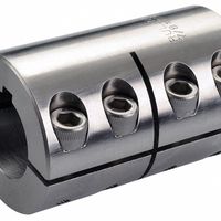
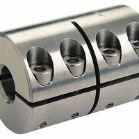
2. **Clamp or Split Muff Coupling**: This coupling is similar to the sleeve coupling but is split into two halves. The halves are bolted together around the shafts, providing a strong grip. This design allows for easier installation and removal without moving the shafts, making it suitable for applications requiring frequent maintenance.
3. **Flange Coupling**: Comprising two separate flanges, each mounted on the shaft ends, this type of coupling is bolted together to form a rigid connection. Flange couplings are robust and can handle higher torque and power transmission, making them ideal for heavy-duty applications. They require precise alignment and are often used in high-speed or high-torque scenarios.
4. **Rigid Box Coupling**: This coupling consists of a box-like structure that encloses the shaft ends. It is bolted or welded to the shafts, providing a very strong and rigid connection. Rigid box couplings are used in applications where maximum rigidity and strength are required, such as in heavy machinery.
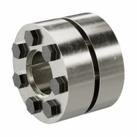
5. **Compression Coupling**: This type uses a compression mechanism to hold the shafts together. It involves a sleeve with a tapered bore and a matching tapered ring. When the ring is tightened, it compresses the sleeve onto the shafts, creating a secure connection. Compression couplings are used where quick assembly and disassembly are needed.
Each type of rigid coupling is chosen based on the specific requirements of the application, such as torque capacity, ease of assembly, and alignment precision.
How do rigid couplings differ from flexible couplings?
Rigid couplings and flexible couplings serve to connect two shafts in mechanical systems but differ significantly in design and application.
Rigid couplings are designed to connect two shafts so that they function as a single unit. They do not allow for any misalignment between the shafts. This type of coupling is ideal for applications where precise alignment is possible and necessary, such as in high-precision machinery. Rigid couplings are simple in design, often consisting of a single piece or two halves bolted together, and are typically used in applications where the shafts are already aligned and do not require any movement. They are known for their high torque transmission capability and are used in situations where maintaining alignment is critical.
Flexible couplings, on the other hand, are designed to accommodate misalignment between connected shafts. They can handle angular, parallel, and axial misalignments, as well as absorb shock loads and vibrations. This flexibility is achieved through various designs, such as elastomeric elements, gear teeth, or metallic discs, which allow for some movement between the shafts. Flexible couplings are used in applications where perfect alignment is difficult to achieve or maintain, such as in systems subject to thermal expansion, vibration, or where the shafts are mounted on separate supports. They help in reducing wear and tear on the connected equipment by compensating for misalignment and dampening vibrations.
In summary, the primary difference lies in their ability to handle misalignment: rigid couplings require precise alignment, while flexible couplings accommodate misalignment and provide additional benefits like vibration damping.
What are the advantages of using rigid couplings?
Rigid couplings offer several advantages in mechanical systems:
1. **Alignment Precision**: Rigid couplings ensure precise alignment between connected shafts, which is crucial for applications requiring exact positioning and minimal misalignment.
2. **Torque Transmission**: They provide efficient torque transmission without any loss, as there is no flexibility or backlash in the connection, making them ideal for high-torque applications.
3. **Simplicity and Cost-Effectiveness**: Rigid couplings are simple in design and easy to install, often resulting in lower costs compared to more complex flexible couplings.
4. **Durability and Maintenance**: With fewer moving parts and no flexible elements, rigid couplings are generally more durable and require less maintenance, reducing downtime and operational costs.
5. **Vibration and Noise Reduction**: In systems where alignment is perfect, rigid couplings can help reduce vibration and noise, contributing to smoother operation.
6. **Compact Design**: They are typically more compact than flexible couplings, which can be advantageous in space-constrained applications.
7. **High-Speed Capability**: Rigid couplings can handle high-speed applications effectively, as they do not introduce additional dynamic forces that could lead to imbalance.
8. **Material Versatility**: Available in various materials, rigid couplings can be selected to match the specific requirements of the application, such as corrosion resistance or high-temperature performance.
9. **Load Distribution**: They distribute loads evenly across the connected shafts, which can enhance the lifespan of the components involved.
10. **No Wear and Tear**: Since there are no flexible elements, rigid couplings do not suffer from wear and tear due to flexing, which can be a concern with flexible couplings.
These advantages make rigid couplings suitable for applications where precise alignment and robust torque transmission are critical, such as in machine tools, conveyor systems, and other industrial machinery.
How do you install a rigid coupling?
1. **Preparation**: Ensure the shafts are clean and free from burrs or damage. Verify that the coupling and shafts are compatible in size and type.
2. **Alignment**: Align the shafts as accurately as possible. Use a straightedge or dial indicator to check for parallel and angular misalignment. Proper alignment is crucial to prevent stress and wear.
3. **Positioning**: Slide the coupling onto one of the shafts. If the coupling is a two-piece type, separate the halves and position them on each shaft.
4. **Assembly**: If using a one-piece coupling, slide it over the second shaft. For a two-piece coupling, bring the halves together around the shafts and ensure they fit snugly.
5. **Fastening**: Tighten the set screws or bolts evenly. If the coupling uses clamping screws, tighten them in a crisscross pattern to ensure even pressure distribution. Use a torque wrench to apply the recommended torque specified by the manufacturer.
6. **Recheck Alignment**: After fastening, recheck the alignment to ensure that the installation process did not disturb the initial alignment.
7. **Final Inspection**: Verify that all screws or bolts are securely tightened and that the coupling is properly seated on the shafts. Check for any signs of stress or misalignment.
8. **Test Run**: Start the machinery at a low speed to observe the coupling in operation. Listen for unusual noises and check for vibrations, which may indicate misalignment or improper installation.
9. **Maintenance**: Regularly inspect the coupling for wear, alignment, and tightness of fasteners to ensure long-term reliability.
What materials are rigid couplings typically made from?
Rigid couplings are typically made from materials that offer high strength, durability, and resistance to wear and environmental factors. Common materials include:
1. **Steel**: Often used for its strength and durability, steel is a popular choice for rigid couplings. It can be further categorized into carbon steel and stainless steel. Carbon steel is cost-effective and provides good tensile strength, while stainless steel offers corrosion resistance, making it suitable for harsh environments.
2. **Aluminum**: Known for its lightweight and corrosion-resistant properties, aluminum is used in applications where weight reduction is crucial. It is not as strong as steel but provides sufficient strength for many applications, especially in aerospace and automotive industries.
3. **Cast Iron**: This material is used for its excellent machinability and vibration damping properties. Cast iron couplings are typically used in heavy-duty applications where the coupling needs to absorb shock and vibration.
4. **Brass**: Brass is used for its corrosion resistance and ease of machining. It is suitable for applications where electrical conductivity is required, such as in certain types of electrical equipment.
5. **Bronze**: Similar to brass, bronze offers good corrosion resistance and is often used in marine applications. It also provides good wear resistance, making it suitable for high-load applications.
6. **Composite Materials**: In some advanced applications, composite materials like carbon fiber or reinforced plastics are used. These materials offer high strength-to-weight ratios and are resistant to corrosion and chemical exposure.
7. **Titanium**: Used in specialized applications where high strength, low weight, and corrosion resistance are required. Titanium is more expensive but offers superior performance in demanding environments.
These materials are selected based on the specific requirements of the application, including load capacity, environmental conditions, and cost considerations.
How do keyless locking rigid couplings work?
Keyless locking rigid couplings work by using frictional force to connect two shafts without the need for keys, splines, or other mechanical interlocking devices. These couplings consist of a sleeve and a set of tapered rings or cones that fit over the shafts to be connected. When the coupling is tightened, usually by a series of screws or bolts, the tapered rings are drawn together, creating a radial force that compresses the sleeve onto the shafts.
The process begins with the coupling being placed over the ends of the shafts. As the screws are tightened, the tapered rings move axially, causing the inner diameter of the sleeve to decrease. This reduction in diameter generates a high-pressure contact between the sleeve and the shaft surfaces, creating a strong frictional bond. The frictional force is sufficient to transmit torque and axial loads between the shafts without any relative motion.
Keyless locking couplings offer several advantages. They eliminate the need for machining keyways, which can weaken shafts and introduce stress concentrations. They also allow for easy adjustment and alignment, as the coupling can be repositioned along the shaft without disassembly. Additionally, they provide uniform stress distribution, reducing the risk of shaft fatigue and failure.
These couplings are particularly useful in applications requiring high torque transmission, precise positioning, or frequent assembly and disassembly. They are commonly used in industries such as manufacturing, robotics, and automotive, where reliability and ease of maintenance are critical.
What are the common applications for shaft adapters?
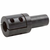
Shaft adapters are versatile components used in various applications to modify or extend the functionality of shafts in mechanical systems. Common applications include:
1. **Size Conversion**: Shaft adapters are often used to convert shafts from one diameter to another, allowing components with different bore sizes to be connected. This is useful in retrofitting or upgrading machinery without replacing entire systems.
2. **Alignment Correction**: They help in correcting misalignments between shafts and components, ensuring smooth operation and reducing wear and tear on machinery.
3. **Extension**: Shaft adapters can extend the length of a shaft, enabling the connection of components that are spaced apart. This is particularly useful in applications where space constraints prevent the use of longer shafts.
4. **Coupling Different Shaft Types**: They facilitate the connection of shafts with different end types, such as keyed, splined, or threaded ends, enhancing compatibility between diverse mechanical components.
5. **Torque Transmission**: In power transmission systems, shaft adapters are used to transmit torque between shafts of different sizes or types, ensuring efficient power transfer in machinery like conveyors, pumps, and compressors.
6. **Repair and Maintenance**: They are used in maintenance and repair operations to replace worn-out or damaged shaft sections without the need for complete shaft replacement, saving time and costs.
7. **Customization**: Shaft adapters allow for customization of machinery by enabling the integration of specialized components, such as sensors or encoders, which may require specific shaft configurations.
8. **Vibration Damping**: Some shaft adapters are designed to dampen vibrations, improving the stability and longevity of mechanical systems.
9. **Prototyping and Testing**: In R&D, shaft adapters are used to quickly assemble and test different configurations of mechanical systems, facilitating rapid prototyping and experimentation.
These applications highlight the importance of shaft adapters in enhancing the flexibility, efficiency, and functionality of mechanical systems across various industries.


