Call +(254) 703 030 000 / 751 483 999 / 721 704 777
.....Read More
Frequently Asked Questions
What is a relay and how does it work?
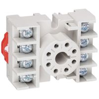
A relay is an electrically operated switch used to control a circuit by a separate low-power signal or multiple circuits by one signal. It consists of an electromagnet, an armature, a spring, and one or more sets of contacts. When an electric current passes through the coil, it generates a magnetic field that attracts the armature. This movement either makes or breaks a connection with the contacts, thus opening or closing the circuit.
Relays are used to control a high-power circuit with a low-power signal, providing isolation between the control and the controlled circuits. They are essential in applications where it is necessary to control a large amount of power with a small input signal, such as in automotive systems, industrial machinery, and home appliances.
There are various types of relays, including electromagnetic relays, solid-state relays, and reed relays, each suited for different applications. Electromagnetic relays are the most common, using a physical movement to open or close contacts. Solid-state relays use semiconductor devices to perform switching without moving parts, offering faster operation and longer life. Reed relays use a pair of magnetic reeds sealed in a glass tube, activated by an external magnetic field.
Relays can be configured in different ways, such as normally open (NO) or normally closed (NC), depending on whether the circuit is open or closed when the relay is not energized. They can also be used in more complex arrangements like latching relays, which maintain their state after being actuated, or time-delay relays, which introduce a delay before switching.
Overall, relays are crucial components in electrical systems, providing control, protection, and signal amplification.
What are the different types of relays and their applications?
1. **Electromechanical Relays**: Use physical moving parts to open or close contacts. Commonly used in industrial applications for switching, motor control, and protection systems.
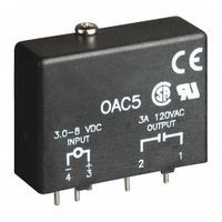
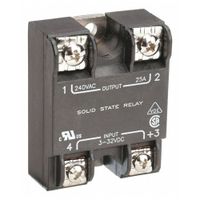
2. **Solid State Relays (SSR)**: Use semiconductor devices to switch without moving parts. Ideal for applications requiring high-speed switching and long life, such as in lighting and heating controls.
3. **Reed Relays**: Consist of reed switches encased in a coil. Used in applications requiring fast operation and low power, like telecommunications and test equipment.
4. **Thermal Relays**: Operate based on temperature changes. Used for motor protection by detecting overloads and overheating.
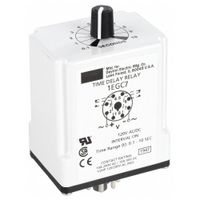
5. **Time Delay Relays**: Provide a delay before switching. Used in industrial automation for sequencing operations and controlling processes.
6. **Overcurrent Relays**: Detect excessive current flow and trip circuits to prevent damage. Common in power distribution systems for protection.
7. **Differential Relays**: Compare the difference between two or more electrical quantities. Used in transformers and generators for fault detection.
8. **Distance Relays**: Measure the impedance of a line to detect faults. Used in transmission line protection.
9. **Buchholz Relays**: Detect gas accumulation in oil-filled transformers. Used for transformer protection.
10. **Polarized Relays**: Use a permanent magnet to enhance sensitivity. Used in telecommunication and signaling applications.
11. **Latching Relays**: Maintain their position after being actuated. Used in memory storage applications and power-saving circuits.
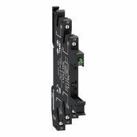
12. **Relay Modules**: Combine multiple relays in a single unit for complex control systems. Used in automation and control panels.
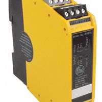
13. **Safety Relays**: Ensure safety by monitoring and controlling safety-critical functions. Used in machinery and process safety systems.
How do you choose the right relay for a specific application?
To choose the right relay for a specific application, consider the following factors:
1. **Load Type and Rating**: Determine the type of load (resistive, inductive, capacitive) and its voltage and current requirements. Ensure the relay can handle the maximum load current and voltage.
2. **Coil Voltage and Type**: Select a relay with a coil voltage compatible with your control circuit. Decide between AC or DC coil types based on your application.
3. **Contact Configuration**: Choose the appropriate contact configuration (SPST, SPDT, DPDT, etc.) based on the number of circuits you need to control and the switching requirements.
4. **Switching Capacity**: Ensure the relay can handle the inrush current and has the necessary switching capacity for your application.
5. **Operating Environment**: Consider the environmental conditions such as temperature, humidity, and exposure to dust or chemicals. Choose a relay with suitable protection (e.g., sealed or hermetically sealed) for harsh environments.
6. **Size and Mounting**: Ensure the relay fits within the available space and is compatible with your mounting requirements (e.g., PCB mount, DIN rail, panel mount).
7. **Response Time**: Consider the relay's response time if your application requires fast switching.
8. **Life Expectancy**: Evaluate the relay's mechanical and electrical life expectancy to ensure it meets the application's durability requirements.
9. **Isolation Requirements**: Ensure the relay provides adequate isolation between the control and load circuits, especially in high-voltage applications.
10. **Regulatory Compliance**: Verify that the relay meets relevant industry standards and certifications for safety and performance.
11. **Cost and Availability**: Consider the cost-effectiveness and availability of the relay, ensuring it fits within your budget and is readily available for replacement or scaling.
By evaluating these factors, you can select a relay that meets the specific needs of your application.
What are the advantages of using solid-state relays over electromechanical relays?
Solid-state relays (SSRs) offer several advantages over electromechanical relays (EMRs):
1. **Longevity and Reliability**: SSRs have no moving parts, which reduces wear and tear, leading to a longer lifespan and higher reliability compared to EMRs, which rely on mechanical contacts that can degrade over time.
2. **Silent Operation**: SSRs operate silently as they do not have mechanical contacts that produce noise when switching, unlike EMRs which can be noisy due to the clicking sound of contacts.
3. **Faster Switching**: SSRs can switch on and off much faster than EMRs, making them suitable for applications requiring rapid cycling.
4. **Reduced Electromagnetic Interference (EMI)**: The absence of arcing and bouncing contacts in SSRs minimizes EMI, which is beneficial in sensitive electronic environments.
5. **Vibration and Shock Resistance**: SSRs are more resistant to vibration and shock because they lack mechanical components, making them ideal for harsh environments.
6. **Low Power Consumption**: SSRs typically consume less power to operate, as they do not require a coil to be energized, unlike EMRs.
7. **No Contact Wear**: Since SSRs do not have physical contacts, there is no contact erosion, which is a common issue in EMRs due to arcing.
8. **Consistent Performance**: SSRs provide consistent performance over their lifespan, as they are not subject to the mechanical fatigue that affects EMRs.
9. **Compact Size**: SSRs are often more compact than EMRs, allowing for more efficient use of space in electronic designs.
10. **Improved Safety**: SSRs can be designed with built-in protection features such as over-voltage and over-current protection, enhancing safety in applications.
These advantages make SSRs a preferred choice in many modern applications, especially where reliability, speed, and noise reduction are critical.
How do time-delay relays function and where are they used?
Time-delay relays function by introducing a predetermined delay in the operation of their contacts after the coil is energized or de-energized. They consist of a timing circuit and a set of contacts. When the relay coil is energized, the timing circuit begins counting down the preset delay period. Once the delay period elapses, the contacts change state, either opening or closing, depending on the relay's configuration. The delay can be set for a specific duration, ranging from milliseconds to several hours, depending on the application.
There are two main types of time-delay relays: on-delay and off-delay. In an on-delay relay, the delay period starts when the coil is energized, and the contacts change state after the delay. In an off-delay relay, the contacts change state immediately when the coil is energized, and the delay period starts when the coil is de-energized, with the contacts reverting to their original state after the delay.
Time-delay relays are used in various applications across industries. They are commonly found in industrial automation systems, where they control the timing of operations such as motor starting and stopping, conveyor belt sequencing, and process control. In HVAC systems, they manage the timing of fan and compressor operations to ensure efficient energy use. In lighting systems, they provide delayed switching to prevent sudden changes in illumination. Additionally, they are used in safety systems to ensure that equipment operates in a safe sequence, preventing accidents and equipment damage. Time-delay relays are also employed in telecommunications and power distribution systems to manage the timing of signal transmission and circuit protection.
What are the common causes of relay failure and how can they be prevented?
Common causes of relay failure include:
1. **Contact Wear and Tear**: Frequent operation can lead to erosion and pitting of contacts. Prevention involves using relays with appropriate contact ratings and employing arc suppression techniques.
2. **Coil Burnout**: Overvoltage or excessive current can cause coil overheating. Prevent by ensuring correct voltage levels and using protective devices like fuses.
3. **Mechanical Fatigue**: Repeated mechanical operations can lead to wear of moving parts. Use relays with higher mechanical endurance ratings and perform regular maintenance.
4. **Contamination**: Dust, dirt, or moisture can affect relay performance. Use sealed relays or enclosures to protect against environmental factors.
5. **Corrosion**: Exposure to corrosive environments can degrade contacts. Use relays with corrosion-resistant materials or coatings.
6. **Electrical Overload**: Exceeding the relay's current or voltage ratings can cause failure. Ensure proper sizing and use of overload protection devices.
7. **Temperature Extremes**: High or low temperatures can affect relay operation. Use relays rated for the specific temperature range of the application.
8. **Vibration and Shock**: Mechanical stress from vibration or shock can damage relays. Use vibration-resistant relays and secure mounting.
9. **Improper Installation**: Incorrect wiring or mounting can lead to failure. Follow manufacturer guidelines and ensure proper installation practices.
10. **Aging**: Over time, materials degrade naturally. Regular testing and replacement of aging relays can prevent failures.
Prevention strategies include selecting the right relay for the application, regular maintenance, environmental protection, and using protective devices to manage electrical and mechanical stresses.
How do you test and troubleshoot a relay?
To test and troubleshoot a relay, follow these steps:
1. **Visual Inspection**: Check for physical damage, corrosion, or burnt marks on the relay and its connections.
2. **Identify Terminals**: Refer to the relay's datasheet to identify coil terminals and contact terminals (NO, NC, and common).
3. **Coil Resistance Test**: Use a multimeter set to the resistance (ohms) mode. Measure the resistance across the coil terminals. Compare the reading with the specified coil resistance in the datasheet. A very high or infinite resistance indicates an open coil, while a very low resistance suggests a shorted coil.
4. **Continuity Test for Contacts**:
- **De-energized State**: Check continuity between the common terminal and the NC terminal. There should be continuity. There should be no continuity between the common and NO terminal.
- **Energized State**: Apply the rated voltage to the coil terminals. Check for continuity between the common and NO terminal. There should be continuity. The NC terminal should now show no continuity with the common.
5. **Voltage Test**: With the relay in the circuit, measure the voltage across the coil when energized. It should match the rated coil voltage.
6. **Contact Voltage Drop Test**: Measure the voltage drop across the closed contacts when the relay is energized. A high voltage drop indicates poor contact quality.
7. **Listen for Activation**: When the relay is energized, listen for a clicking sound, indicating the armature is moving.
8. **Check for Mechanical Issues**: If the relay doesn't click, inspect for mechanical obstructions or debris preventing movement.
9. **Replace if Necessary**: If any tests fail, replace the relay with a new one of the same specifications.
By following these steps, you can effectively test and troubleshoot a relay to ensure it functions correctly.
