Call +(254) 703 030 000 / 751 483 999 / 721 704 777
.....Read More
Frequently Asked Questions
What are the different types of bench test leads and their uses?
Bench test leads are essential tools in electronics testing and prototyping. Here are the different types and their uses:
1. **Alligator Clips**: These leads have spring-loaded jaws that can grip components or wires. They are used for temporary connections, testing circuits, and connecting to terminals or battery contacts.
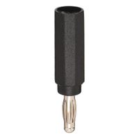
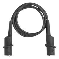
2. **Banana Plugs**: These leads have a cylindrical metal pin that fits into banana jacks. They are used for connecting to multimeters, power supplies, and other test equipment, providing a secure and reliable connection.
3. **BNC Connectors**: These leads have a bayonet-style connector used for RF signals and oscilloscope connections. They are ideal for high-frequency applications and provide a quick and secure connection.
4. **Crocodile Clips**: Similar to alligator clips but generally larger, these are used for connecting to larger components or bus bars. They provide a strong grip and are used in high-current applications.
5. **Test Probes**: These leads have pointed metal tips for precise contact with circuit points. They are used with multimeters and oscilloscopes for measuring voltage, current, and resistance.
6. **Hook Clips**: These leads have a small hook that can latch onto component leads or wires. They are used for connecting to small or delicate components without causing damage.
7. **IC Test Clips**: These are designed to clip onto integrated circuits, allowing for easy testing of IC pins without soldering. They are used in troubleshooting and prototyping.
8. **SMD Tweezers**: These are specialized leads for testing surface-mount devices. They allow for easy connection to small SMD components.
9. **Stackable Leads**: These have banana plugs that can be stacked, allowing multiple connections to a single point. They are used in complex testing setups.
Each type of lead serves a specific purpose, ensuring accurate and efficient testing in various electronic applications.
How do you properly connect test instruments to a device being monitored?
1. **Identify Test Points**: Determine the specific points on the device where measurements are needed, such as voltage, current, or signal paths.
2. **Select Appropriate Instruments**: Choose the right test instruments (e.g., multimeter, oscilloscope, signal generator) based on the parameters to be measured.
3. **Ensure Instrument Calibration**: Verify that all test instruments are calibrated to ensure accurate readings.
4. **Power Off the Device**: Before connecting, ensure the device is powered off to prevent accidental short circuits or damage.
5. **Use Proper Probes and Leads**: Select probes and leads that are compatible with both the test instrument and the device under test. Ensure they are rated for the expected voltage and current levels.
6. **Connect Ground First**: Always connect the ground lead first to minimize the risk of electric shock and to provide a reference point for measurements.
7. **Attach Probes Securely**: Connect the probes to the identified test points securely. Use clips or hooks if necessary to ensure a stable connection.
8. **Observe Polarity**: Pay attention to the polarity of the connections, especially when measuring DC voltages or currents.
9. **Power On the Device**: Once all connections are secure, power on the device to begin monitoring.
10. **Monitor and Record Data**: Observe the readings on the test instruments and record the data as needed for analysis.
11. **Disconnect Safely**: After measurements are complete, power off the device and disconnect the probes, starting with the ground lead.
12. **Review Safety Protocols**: Always follow safety protocols and wear appropriate personal protective equipment (PPE) to prevent accidents.
13. **Document Results**: Keep a detailed record of the test setup and results for future reference and troubleshooting.
What are the best practices for using bench test clips and probes?
1. **Safety First**: Always ensure the equipment is powered off before attaching or removing clips and probes to prevent electric shock or damage.
2. **Proper Connection**: Use the correct type of clip or probe for the component being tested. Ensure a secure and stable connection to avoid inaccurate readings.
3. **Minimize Interference**: Keep probe leads as short as possible to reduce inductance and capacitance, which can affect measurements. Use shielded cables if necessary.
4. **Correct Grounding**: Ensure proper grounding to prevent noise and interference. Use a common ground point for all measurements.
5. **Avoid Overloading**: Check the voltage and current ratings of the clips and probes to prevent overloading, which can lead to equipment damage or inaccurate readings.
6. **Calibration**: Regularly calibrate probes and clips to maintain accuracy. Follow manufacturer guidelines for calibration procedures.
7. **Use Appropriate Tools**: Select the right probe tip for the application, such as needle tips for small components or alligator clips for larger connections.
8. **Maintain Cleanliness**: Keep clips and probes clean to ensure good electrical contact. Use isopropyl alcohol to clean contacts if necessary.
9. **Organize Leads**: Keep leads organized and untangled to prevent accidental disconnection or short circuits.
10. **Documentation**: Record settings and configurations for repeatability and troubleshooting.
11. **Training**: Ensure users are trained in the proper use of test equipment to prevent misuse and ensure safety.
12. **Regular Inspection**: Inspect clips and probes for wear and damage before use. Replace any damaged components immediately.
13. **Environmental Considerations**: Be aware of environmental factors such as temperature and humidity that may affect measurements.
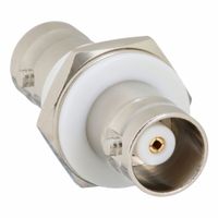
How do BNC adapters work with coaxial cables?
BNC (Bayonet Neill-Concelman) adapters work with coaxial cables by providing a secure and reliable connection between different types of coaxial cables or between coaxial cables and devices. They are designed to connect cables with BNC connectors, which are commonly used in radio, television, and other RF applications.
The BNC adapter consists of a male and female connector. The male connector has a central pin that fits into the female connector's socket. The outer part of the connector has a bayonet mount, which includes two small pins on the male connector that fit into slots on the female connector. To secure the connection, the male connector is inserted into the female connector and then twisted, locking the pins into place. This bayonet coupling mechanism ensures a quick and secure connection that is resistant to vibration and accidental disconnection.
Inside the BNC adapter, the central pin of the male connector makes contact with the central conductor of the coaxial cable, while the outer metal shell makes contact with the cable's shielding. This design maintains the coaxial cable's characteristic impedance, typically 50 or 75 ohms, ensuring minimal signal loss and reflection.
BNC adapters can be used to connect cables of different types or lengths, adapt between different connector types, or split or combine signals. They are essential in applications requiring frequent connections and disconnections, such as test equipment, broadcast, and networking environments. The robust design and ease of use make BNC adapters a popular choice for maintaining signal integrity in various RF and video applications.
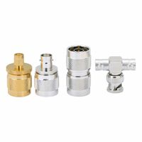
What is the purpose of RF adapter kits in testing environments?
RF adapter kits are essential in testing environments for several reasons. They provide the necessary connectivity between different types of RF connectors, ensuring compatibility and seamless signal transmission. This is crucial in testing scenarios where various devices and equipment may have different connector types, such as SMA, BNC, N-type, or TNC.
The primary purpose of RF adapter kits is to facilitate accurate and efficient testing by minimizing signal loss and maintaining the integrity of the signal being tested. High-quality adapters ensure that the signal's characteristics are preserved, which is vital for obtaining reliable test results.
Additionally, RF adapter kits enhance the flexibility and versatility of testing setups. They allow engineers and technicians to quickly adapt to different testing requirements without the need for multiple dedicated cables or connectors. This adaptability is particularly important in dynamic testing environments where equipment configurations may frequently change.
RF adapter kits also contribute to cost-effectiveness by reducing the need for purchasing multiple cables or connectors for each specific test setup. Instead, a single kit can provide the necessary adapters to accommodate various configurations, saving both time and resources.
Furthermore, these kits often include a range of adapters that cover a wide frequency range, ensuring compatibility with different RF applications. This broad frequency coverage is essential for testing environments that deal with diverse RF technologies, from low-frequency applications to high-frequency microwave systems.
In summary, RF adapter kits are crucial in testing environments for ensuring compatibility, preserving signal integrity, enhancing flexibility, and providing cost-effective solutions for diverse RF testing needs.
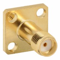
How do SMA adapters and terminations ensure compatibility in RF systems?
SMA adapters and terminations ensure compatibility in RF systems through several key features:
1. **Standardization**: SMA (SubMiniature version A) connectors are standardized, ensuring that they can interconnect with other SMA components regardless of the manufacturer. This standardization includes specific dimensions, materials, and performance criteria, which ensures a consistent interface.
2. **Impedance Matching**: SMA connectors are typically designed for 50-ohm impedance, which is standard in RF systems. This impedance matching minimizes signal reflection and loss, ensuring efficient power transfer and maintaining signal integrity across connections.
3. **Frequency Range**: SMA connectors and adapters are capable of operating at frequencies up to 18 GHz or higher, making them suitable for a wide range of RF applications. This broad frequency range ensures that they can be used in various systems without compatibility issues.
4. **Mechanical Compatibility**: The threaded coupling mechanism of SMA connectors provides a secure and reliable connection, preventing accidental disconnections and ensuring consistent performance. This mechanical design also allows for repeated connections and disconnections without significant wear.
5. **Material and Construction**: SMA adapters and terminations are typically made from high-quality materials such as stainless steel or brass with gold or silver plating. These materials provide excellent conductivity and corrosion resistance, ensuring long-term reliability and performance.
6. **Versatility**: SMA adapters are available in various configurations, such as male-to-female, female-to-female, and male-to-male, allowing for flexible interconnections between different components. Terminations provide a means to properly terminate unused ports, preventing signal leakage and maintaining system integrity.
By addressing these aspects, SMA adapters and terminations ensure that RF systems can operate efficiently and reliably, maintaining compatibility across different components and applications.
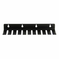
What are the benefits of using test lead holders for storage?
Test lead holders offer several benefits for storage:
1. **Organization**: They keep test leads neatly arranged, preventing tangling and making it easier to identify and access the required leads quickly.
2. **Space Efficiency**: By holding leads in a compact manner, they save space in toolboxes or workstations, allowing for more efficient use of storage areas.
3. **Protection**: Test lead holders protect leads from physical damage, such as bending or fraying, which can occur when leads are loosely stored.
4. **Durability**: Proper storage in holders can extend the lifespan of test leads by preventing wear and tear, reducing the need for frequent replacements.
5. **Portability**: They make it easier to transport test leads without them becoming tangled or damaged, which is particularly useful for technicians who need to move between job sites.
6. **Safety**: By keeping leads organized and off the floor or work surfaces, holders reduce the risk of tripping hazards and accidental damage to the leads or other equipment.
7. **Efficiency**: Quick access to organized leads can improve workflow efficiency, reducing the time spent searching for the right lead and allowing more focus on the task at hand.
8. **Professionalism**: A tidy and organized workspace reflects professionalism and attention to detail, which can be important in client-facing environments.
9. **Customization**: Many holders allow for customization, enabling users to label or color-code leads for specific tasks or equipment, further enhancing organization and efficiency.
10. **Versatility**: Test lead holders can accommodate various types and sizes of leads, making them a versatile storage solution for different testing equipment.