.....Read More

Frequently Asked Questions

What is electronic bench testing and how does it work?

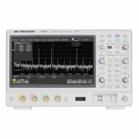
Electronic bench testing is a process used to evaluate the performance, functionality, and reliability of electronic components, circuits, or systems in a controlled environment. It involves using specialized equipment and tools to simulate real-world conditions and measure various parameters to ensure the device meets its specifications. The process typically begins with setting up the device under test (DUT) on a workbench equipped with necessary instruments like oscilloscopes, multimeters, signal generators, and power supplies. The DUT is connected to these instruments to monitor its behavior under different conditions. During testing, various input signals are applied to the DUT to simulate operational scenarios. The response of the DUT is observed and measured using the connected instruments. Key parameters such as voltage, current, frequency, and signal integrity are analyzed to assess performance. Test procedures may include functional testing, where the device's basic operations are verified; stress testing, which subjects the device to extreme conditions to evaluate its limits; and compliance testing, ensuring the device meets industry standards and regulations. Data collected during testing is analyzed to identify any deviations from expected performance. Engineers use this information to diagnose issues, optimize design, and ensure quality control. Bench testing is crucial in the development phase to catch defects early, reducing the risk of failure in the field. Overall, electronic bench testing is an essential step in the design and manufacturing process, providing valuable insights into the device's capabilities and ensuring it operates reliably in its intended application.

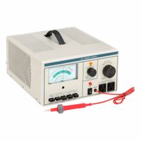
How do bench testing power supplies convert AC to DC power?

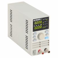
Bench testing power supplies convert AC to DC power through a multi-stage process involving transformation, rectification, filtering, and regulation: 1. **Transformation**: The process begins with a transformer, which adjusts the incoming AC voltage to a desired level. The transformer can either step down or step up the voltage depending on the requirements of the power supply. This stage isolates the power supply from the AC mains and provides safety and voltage adjustment. 2. **Rectification**: The transformed AC voltage is then passed through a rectifier, typically composed of diodes. The rectifier converts the AC voltage, which alternates in polarity, into a pulsating DC voltage. Common rectifier configurations include half-wave, full-wave, and bridge rectifiers, with the bridge rectifier being the most efficient and widely used. 3. **Filtering**: The pulsating DC output from the rectifier is not suitable for most electronic devices, as it contains ripples. To smooth out these ripples, the voltage is passed through a filter, usually consisting of capacitors and sometimes inductors. The filter reduces the AC ripple component, resulting in a smoother DC voltage. 4. **Regulation**: The filtered DC voltage may still vary with changes in load or input voltage. A voltage regulator is used to maintain a constant output voltage despite these variations. Regulators can be linear or switching types. Linear regulators provide a stable output with low noise but are less efficient, while switching regulators are more efficient and can handle a wider range of input voltages. 5. **Output**: The regulated DC voltage is then available at the output terminals of the bench power supply, ready to power electronic circuits and devices for testing and development purposes.

What are the benefits of using bench testing equipment over compact models?

Bench testing equipment offers several advantages over compact models: 1. **Comprehensive Testing Capabilities**: Bench testing equipment typically provides a wider range of testing functions and capabilities, allowing for more detailed and comprehensive analysis of components or systems. 2. **Higher Precision and Accuracy**: These models often feature advanced technology and components that deliver higher precision and accuracy in measurements, which is crucial for research and development applications. 3. **Scalability**: Bench models can often be expanded or customized with additional modules or features, making them suitable for evolving testing needs and more complex testing scenarios. 4. **Robustness and Durability**: Designed for frequent and intensive use, bench testing equipment is generally more robust and durable, ensuring longevity and reliability in demanding environments. 5. **Advanced Features**: They often include advanced features such as automated testing sequences, data logging, and analysis software, which enhance productivity and ease of use. 6. **Better Heat Dissipation**: Larger bench models typically have better heat dissipation mechanisms, which is important for maintaining performance and preventing overheating during extended testing sessions. 7. **User Interface and Display**: Bench equipment usually comes with larger, more detailed displays and user interfaces, facilitating easier operation and interpretation of results. 8. **Integration with Other Equipment**: They can be more easily integrated with other laboratory or testing equipment, allowing for more complex and comprehensive testing setups. 9. **Professional and Industrial Use**: Bench models are often preferred in professional and industrial settings where the highest level of testing accuracy and reliability is required. 10. **Support and Maintenance**: Manufacturers often provide more extensive support and maintenance options for bench models, ensuring they remain operational and up-to-date with the latest technology advancements.

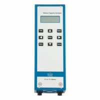
How do battery capacity analyzers determine remaining voltage?

Battery capacity analyzers determine remaining voltage by measuring the open-circuit voltage (OCV) of the battery. The OCV is the voltage of the battery when it is not under any load, providing an indication of the state of charge (SOC). The analyzer connects to the battery terminals and measures the voltage using a high-impedance voltmeter to ensure minimal current draw, which could otherwise affect the reading. The analyzer may also perform a load test, where a known load is applied to the battery for a specific duration. During this test, the voltage drop is measured, and the battery's ability to maintain voltage under load is assessed. This helps in determining the battery's health and capacity. Advanced analyzers use algorithms and battery models to interpret the voltage readings in relation to the battery's chemistry and temperature. They may also incorporate impedance spectroscopy, where the battery's internal resistance is measured at different frequencies. This data helps in understanding the battery's condition and estimating the remaining capacity more accurately. Temperature sensors are often used to compensate for temperature effects on voltage readings, as battery voltage can vary with temperature changes. The analyzer may also store historical data to track the battery's performance over time, providing insights into its aging and degradation. In summary, battery capacity analyzers use a combination of voltage measurement, load testing, impedance analysis, and temperature compensation to determine the remaining voltage and overall health of a battery.

What is the role of antistatic safety equipment in electronic testing?

Antistatic safety equipment plays a crucial role in electronic testing by preventing electrostatic discharge (ESD), which can damage sensitive electronic components. ESD occurs when there is a sudden flow of electricity between two electrically charged objects, often caused by contact, an electrical short, or dielectric breakdown. This discharge can destroy or degrade electronic circuits, leading to malfunctions or complete failure of electronic devices. Antistatic equipment includes items such as wrist straps, mats, bags, and clothing designed to safely dissipate static electricity. Wrist straps are worn by technicians to ground themselves, ensuring that any static charge they carry is transferred safely to the ground rather than to the electronic components. Antistatic mats provide a grounded surface on which electronic devices can be placed during testing, preventing the buildup of static electricity. Antistatic bags are used to store and transport electronic components, protecting them from static charges in the environment. In addition to these, antistatic clothing, such as lab coats and gloves, is worn to minimize the risk of static generation from the body or clothing. These garments are made from conductive or dissipative materials that help in neutralizing static charges. The use of antistatic safety equipment is essential in environments where electronic testing is conducted, such as laboratories, manufacturing facilities, and repair shops. It ensures the integrity and reliability of electronic components by preventing ESD-related damage, thereby reducing the risk of costly repairs, replacements, and downtime. By maintaining a controlled environment free from static electricity, antistatic equipment helps in achieving accurate testing results and prolongs the lifespan of electronic devices.

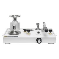
How do bench pressure calibrators ensure accurate measurements?

Bench pressure calibrators ensure accurate measurements through several key mechanisms: 1. **Precision Components**: They use high-quality sensors and transducers that are calibrated against known standards. These components are designed to have minimal drift and high repeatability, ensuring consistent performance over time. 2. **Calibration Standards**: Bench pressure calibrators are calibrated using traceable standards, often to national or international standards like NIST or ISO. This traceability ensures that the measurements are accurate and can be relied upon for critical applications. 3. **Environmental Control**: Many bench pressure calibrators are equipped with features to compensate for environmental factors such as temperature, humidity, and barometric pressure, which can affect measurement accuracy. This ensures that the calibrator provides accurate readings regardless of external conditions. 4. **Advanced Electronics**: They incorporate advanced electronics and digital signal processing to enhance measurement accuracy. This includes filtering out noise and compensating for any non-linearities in the sensor response. 5. **User Calibration**: They often allow for user calibration, enabling operators to adjust the calibrator to account for any deviations over time. This feature helps maintain accuracy between factory calibrations. 6. **Self-Diagnostics**: Many models include self-diagnostic features that alert users to potential issues, such as sensor drift or electronic faults, allowing for timely maintenance and recalibration. 7. **High Resolution and Sensitivity**: Bench pressure calibrators typically offer high resolution and sensitivity, allowing for precise adjustments and fine-tuning of pressure measurements. 8. **Data Logging and Analysis**: They often come with data logging capabilities, enabling users to record and analyze measurement data over time. This helps in identifying trends and ensuring long-term accuracy. By integrating these features, bench pressure calibrators provide reliable and accurate pressure measurements essential for various industrial and laboratory applications.

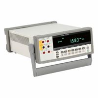
What features should I look for in a bench type digital multimeter?

When selecting a bench type digital multimeter (DMM), consider the following features: 1. **Accuracy and Resolution**: Look for high accuracy and resolution to ensure precise measurements. A DMM with a higher number of counts (e.g., 50,000 counts) provides better resolution. 2. **Measurement Functions**: Ensure it can measure voltage, current, resistance, capacitance, frequency, and temperature. Additional functions like continuity, diode testing, and true RMS for AC measurements are beneficial. 3. **Input Ranges**: Check for a wide range of input measurements to accommodate various testing needs. Auto-ranging capabilities can simplify operation. 4. **Display**: A large, clear, and backlit display enhances readability. Dual display options can show multiple measurements simultaneously. 5. **Connectivity**: USB, RS-232, GPIB, or LAN interfaces allow for data logging and remote control. Consider models with software support for data analysis. 6. **Durability and Build Quality**: A robust design with a solid build ensures longevity. Look for models with protective features like input protection and overload protection. 7. **Calibration and Certification**: Ensure the DMM is calibrated and comes with a certificate of calibration for traceability and compliance with standards. 8. **User Interface**: Intuitive controls and a user-friendly interface make operation easier. Consider models with programmable functions for repetitive tasks. 9. **Size and Portability**: Depending on your workspace, consider the size and weight. Some models offer portability features like carrying handles. 10. **Brand Reputation and Support**: Choose reputable brands known for quality and reliability. Check for warranty, customer support, and availability of service centers. 11. **Price and Budget**: Balance features with your budget. Higher-end models offer more features but ensure they align with your specific needs. 12. **Additional Features**: Consider features like data storage, graphing capabilities, and built-in help menus for enhanced functionality.

How do LCR meters measure inductance, capacitance, and resistance?

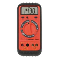
LCR meters measure inductance (L), capacitance (C), and resistance (R) using various techniques, primarily based on impedance measurement. These meters apply an AC signal to the component and measure the resulting voltage and current to determine the impedance, from which L, C, and R values are derived. 1. **Resistance Measurement**: LCR meters measure resistance by applying a known AC voltage and measuring the resulting current. The resistance is calculated using Ohm's Law (R = V/I). For DC resistance, a DC signal is used. 2. **Capacitance Measurement**: To measure capacitance, the meter applies an AC voltage and measures the phase shift and magnitude of the current. The capacitive reactance (Xc) is calculated using the formula Xc = 1/(2πfC), where f is the frequency. The capacitance is then derived from the reactance. 3. **Inductance Measurement**: For inductance, the meter applies an AC signal and measures the phase shift and magnitude of the current. The inductive reactance (Xl) is calculated using Xl = 2πfL. The inductance is derived from the reactance. LCR meters often use bridge circuits, such as the Wheatstone bridge for resistance, and variations like the Maxwell-Wien bridge for inductance and the Schering bridge for capacitance. Modern digital LCR meters use more advanced techniques, such as auto-balancing bridge methods and digital signal processing, to provide accurate measurements over a wide range of frequencies. The choice of test frequency and signal level can affect the accuracy and relevance of the measurements, as components may behave differently at different frequencies. Advanced LCR meters allow users to select these parameters to match the conditions under which the component will be used.

What is the purpose of function and pulse generators in electronic testing?

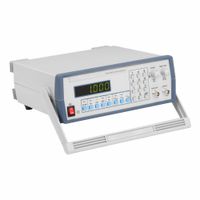
Function and pulse generators are essential tools in electronic testing, serving distinct but complementary purposes. Function generators produce various waveforms, such as sine, square, triangular, and sawtooth waves, over a range of frequencies. They are used to simulate the input signals that electronic devices might encounter in real-world applications. This allows engineers to test and analyze the behavior of circuits under different conditions. Function generators are crucial for tasks like frequency response analysis, filter testing, and signal modulation. They help in verifying the performance and stability of circuits, ensuring that devices operate correctly across their intended frequency ranges. Pulse generators, on the other hand, are specialized for creating precise timing signals, typically in the form of square waves or pulses. They are used to test digital circuits, where timing and synchronization are critical. Pulse generators allow engineers to evaluate the response of digital systems to specific timing sequences, such as clock signals or data pulses. They are vital for testing the functionality of logic gates, microcontrollers, and communication interfaces. Pulse generators also help in assessing the rise and fall times, pulse width, and duty cycle of digital signals, ensuring that circuits meet their design specifications. Both function and pulse generators are indispensable in the design, development, and troubleshooting of electronic systems. They provide controlled, repeatable signals that enable engineers to isolate and diagnose issues, optimize performance, and validate designs before deployment. By simulating real-world conditions, these generators help ensure that electronic devices function reliably and efficiently in their intended applications.

How can I protect sensitive electronics from electrostatic discharge during testing?

To protect sensitive electronics from electrostatic discharge (ESD) during testing, follow these guidelines: 1. **Use ESD-Safe Workstations**: Set up workstations with ESD-safe mats, wrist straps, and grounding points. Ensure all surfaces are conductive and connected to a common ground. 2. **Wear ESD Protective Gear**: Use ESD wrist straps and heel straps to dissipate static charge from your body. Ensure they are properly grounded. 3. **Control Environmental Conditions**: Maintain humidity levels between 40-60% to reduce static buildup. Use ionizers to neutralize static charges in the air. 4. **Use ESD-Safe Tools and Equipment**: Employ tools made from conductive or static-dissipative materials. Ensure test equipment is grounded and ESD-safe. 5. **Handle Components Properly**: Always handle electronic components by the edges. Avoid touching pins or conductive areas. 6. **Use ESD Packaging**: Store and transport components in ESD-safe bags, trays, or containers. Use shielding bags for sensitive components. 7. **Implement ESD Training**: Train personnel on ESD awareness and prevention techniques. Regularly update training to include new standards and practices. 8. **Regularly Test ESD Equipment**: Periodically check wrist straps, mats, and other ESD equipment for proper functionality and grounding. 9. **Establish ESD Procedures**: Develop and enforce standard operating procedures for ESD control. Include steps for setup, testing, and teardown. 10. **Use ESD-Safe Flooring**: Install conductive or static-dissipative flooring to minimize static buildup. 11. **Monitor ESD Events**: Use ESD event detectors to monitor and log ESD incidents, helping identify problem areas. By implementing these measures, you can significantly reduce the risk of ESD damage during testing of sensitive electronics.