Call +(254) 703 030 000 / 751 483 999 / 721 704 777
- Home
- Test Instruments
- Electrical Power Testing
- Multimeters
.....Read More
Frequently Asked Questions
How do I use a multimeter to measure voltage?
To measure voltage with a multimeter, follow these steps:
1. **Select the Multimeter**: Ensure your multimeter is capable of measuring the type of voltage you need (AC or DC). Most digital multimeters can measure both.
2. **Set the Multimeter**: Turn the dial to the appropriate voltage setting. For DC voltage, select the "V" with a straight line. For AC voltage, select the "V" with a wavy line. Choose a range higher than the expected voltage to prevent damage.
3. **Prepare the Probes**: Insert the black probe into the "COM" (common) port and the red probe into the "V" (voltage) port.
4. **Test the Circuit**: Ensure the circuit is powered on. For DC, identify the positive and negative terminals. For AC, polarity does not matter.
5. **Connect the Probes**:
- For DC: Touch the black probe to the negative terminal and the red probe to the positive terminal.
- For AC: Touch the probes to the two points where you want to measure the voltage.
6. **Read the Display**: Observe the multimeter display for the voltage reading. If the reading is negative in DC, reverse the probe connections.
7. **Adjust Range if Necessary**: If the display shows "1" or "OL" (overload), switch to a higher range. If the reading is too low, switch to a lower range for better accuracy.
8. **Turn Off and Store**: After measuring, turn off the multimeter to save battery and store it properly.
Always follow safety precautions, especially when measuring high voltages, to avoid electric shock or damage to the multimeter.
How do I test a battery with a multimeter?
1. **Gather Materials**: Obtain a digital multimeter and the battery you wish to test.
2. **Set Multimeter**: Turn the multimeter dial to the DC voltage setting (V with a straight line), selecting a range higher than the battery's voltage. For example, use the 20V setting for a 9V battery.
3. **Identify Battery Terminals**: Locate the positive (+) and negative (-) terminals on the battery.
4. **Connect Probes**:
- Attach the red probe to the multimeter's VΩmA port.
- Attach the black probe to the COM port.
5. **Test Battery**:
- Touch the red probe to the battery's positive terminal.
- Touch the black probe to the negative terminal.
6. **Read Voltage**: Observe the multimeter display for the voltage reading.
7. **Interpret Results**:
- Compare the reading to the battery's rated voltage (e.g., 1.5V for AA/AAA, 9V for 9V batteries).
- A reading close to the rated voltage indicates a good battery.
- A significantly lower reading suggests the battery is weak or dead.
8. **Safety Precautions**:
- Ensure correct probe placement to avoid short circuits.
- Do not test batteries with visible damage or leakage.
9. **Additional Checks**: For rechargeable batteries, check the voltage after charging to ensure they hold a charge.
10. **Dispose Properly**: If the battery is dead, dispose of it according to local regulations.
What is the difference between AC and DC voltage on a multimeter?
AC (Alternating Current) and DC (Direct Current) voltage measurements on a multimeter differ primarily in the type of current they measure and how they are displayed.
AC voltage refers to the current that periodically reverses direction, typically found in household outlets and power grids. On a multimeter, AC voltage is usually represented by a sine wave symbol (~) or the letters "ACV." When measuring AC voltage, the multimeter calculates the root mean square (RMS) value, which represents the effective voltage level. This is crucial because AC voltage varies over time, and the RMS value provides a consistent measure of its power.
DC voltage, on the other hand, refers to current that flows in a single direction, commonly found in batteries and electronic devices. On a multimeter, DC voltage is indicated by a straight line with a dashed line underneath (⎓) or the letters "DCV." DC voltage is typically stable and does not vary over time, making it straightforward to measure. The multimeter displays the actual voltage level present in the circuit.
When using a multimeter, it is essential to select the correct mode (AC or DC) to ensure accurate readings. Using the wrong setting can lead to incorrect measurements or even damage the multimeter. Additionally, AC voltage measurements may require more complex circuitry within the multimeter to accurately capture the varying signal, while DC voltage measurements are generally simpler due to the steady nature of the current.
How do I measure current with a multimeter?
To measure current with a multimeter, follow these steps:
1. **Turn Off Power**: Ensure the circuit is powered off to safely connect the multimeter.
2. **Select Current Measurement**: Set the multimeter to measure current (A). Choose AC or DC based on your circuit. Start with the highest current range to prevent damage.
3. **Insert Probes**: Connect the black probe to the COM (common) port and the red probe to the port labeled for current (often marked as A or mA).
4. **Break the Circuit**: Identify where you need to measure the current. Disconnect the circuit at that point to insert the multimeter in series.
5. **Connect Probes in Series**: Attach the red probe to the positive side of the break and the black probe to the negative side. This ensures the multimeter becomes part of the circuit.
6. **Power On the Circuit**: Turn the circuit back on. The multimeter will display the current flowing through the circuit.
7. **Read the Measurement**: Observe the reading on the multimeter display. If the reading is too low, switch to a lower range for more accuracy.
8. **Turn Off and Disconnect**: After taking the measurement, turn off the circuit, remove the probes, and restore the circuit to its original state.
9. **Safety Precautions**: Always ensure the multimeter is rated for the current you are measuring. Avoid touching probe tips and ensure connections are secure to prevent short circuits.
10. **Return Settings**: After use, turn off the multimeter and return the dial to a neutral position, such as OFF or V, to preserve battery life.
How do I check for continuity with a multimeter?
To check for continuity with a multimeter, follow these steps:
1. **Turn Off Power**: Ensure the circuit or device you are testing is powered off to prevent damage to the multimeter or injury.
2. **Select Continuity Mode**: Turn the multimeter's dial to the continuity test mode, often indicated by a diode symbol or sound wave icon. Some multimeters combine this with the resistance (ohm) setting.
3. **Test the Multimeter**: Before testing the circuit, touch the multimeter probes together. The multimeter should emit a beep, indicating it is functioning correctly.
4. **Connect Probes to Circuit**: Place the black probe on one end of the component or wire and the red probe on the other end. Polarity is not important in continuity testing.
5. **Interpret Results**:
- **Beep Sound**: If the multimeter beeps, the circuit is continuous, meaning there is a complete path for current flow.
- **No Beep**: If there is no sound, the circuit is open, indicating a break or fault in the path.
- **Display Reading**: Some multimeters display a low resistance value (close to zero) for continuity and "OL" (over limit) for an open circuit.
6. **Check Multiple Points**: If testing a complex circuit, check continuity at various points to isolate the fault.
7. **Safety Precautions**: Always ensure the circuit is de-energized and handle probes carefully to avoid short circuits.
By following these steps, you can effectively use a multimeter to check for continuity in electrical circuits and components.
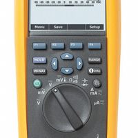
What do the symbols on a multimeter mean?
A multimeter is a versatile tool used to measure electrical properties, and its symbols represent various functions and settings. Here's a breakdown of common symbols:
1. **V**: Represents voltage.
- **V~** or **V AC**: Alternating Current voltage.
- **V—** or **V DC**: Direct Current voltage.
2. **A**: Represents current.
- **A~** or **A AC**: Alternating Current.
- **A—** or **A DC**: Direct Current.
3. **Ω**: Represents resistance, measured in ohms.
4. **mA**: Milliamps, a smaller unit of current.
5. **μA**: Microamps, an even smaller unit of current.
6. **COM**: Common terminal, used for all measurements.
7. **10A** or **20A**: High current measurement terminal.
8. **Diode Symbol**: Used for testing diodes and continuity.
9. **Capacitance Symbol (F)**: Measures capacitance in farads.
10. **Hz**: Frequency measurement in hertz.
11. **Temperature Symbol (°C/°F)**: Measures temperature.
12. **Battery Symbol**: Indicates battery testing mode.
13. **Continuity Symbol (Sound Wave or Diode)**: Tests if a circuit is complete.
14. **Hold Button**: Freezes the current reading on the display.
15. **Auto Range**: Automatically selects the measurement range.
16. **Backlight Symbol**: Indicates the backlight function for the display.
17. **MAX/MIN**: Captures the maximum or minimum value measured.
18. **REL**: Relative measurement mode, sets a reference point.
19. **NCV**: Non-Contact Voltage detection.
20. **Square Wave Symbol**: Indicates a signal output function.
These symbols help users navigate the multimeter's functions, ensuring accurate measurements for various electrical parameters.
How do I use a multimeter to test a wall outlet?
To test a wall outlet with a multimeter, follow these steps:
1. **Safety First**: Ensure your hands are dry and you're standing on a dry surface. Use insulated tools and wear rubber-soled shoes.
2. **Set Up the Multimeter**: Turn the multimeter dial to AC voltage (V~), typically represented by a "V" with a wavy line. Set the range to 200V or higher if it's not auto-ranging.
3. **Test the Outlet**:
- **Insert Probes**: Insert the black probe into the neutral slot (the larger slot) and the red probe into the hot slot (the smaller slot).
- **Read Voltage**: The multimeter should read approximately 110-120 volts in the U.S. or 220-240 volts in many other countries. A significantly lower or higher reading indicates a problem.
4. **Check for Proper Grounding**:
- **Move Black Probe**: Keep the red probe in the hot slot and move the black probe to the ground slot (the round or U-shaped hole).
- **Read Voltage**: The reading should be the same as the previous test. If not, there may be a grounding issue.
5. **Test Neutral to Ground**:
- **Move Red Probe**: Place the red probe in the neutral slot and the black probe in the ground slot.
- **Read Voltage**: The reading should be close to zero. A higher reading indicates a wiring problem.
6. **Turn Off Multimeter**: After testing, turn off the multimeter and remove the probes.
7. **Interpret Results**: If any readings are abnormal, consider consulting a professional electrician to address potential wiring issues.


