.....Read More
Accessories for Multimeters & Clamp Meters
AC Current Line Splitters
Cable Height Meters

Capacitor Testers
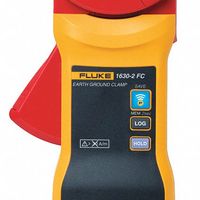
Clamp Meters
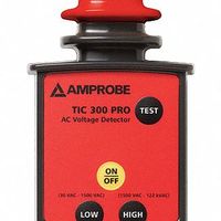
High-Voltage Testers
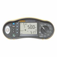
Installation Testers
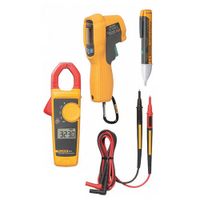
Instrument Combination Kits

Multimeters
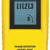
Phasing & Motor Rotation Meters
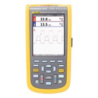
Portable Oscilloscopes & Accessories

Power Quality Testers
Resistance Testers
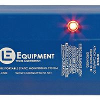
Static Monitoring Systems
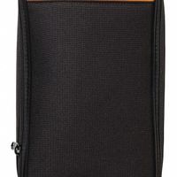
Test Instrument Carrying Cases
Test Leads & Test Probes

USB Testers
Frequently Asked Questions
What is the purpose of electrical power testing devices?
How do multimeters measure voltage, current, and resistance?
What are the advantages of using clamp meters for testing electrical current?
How do test leads and test probes ensure safe and accurate test results?
What types of faults can resistance testers identify in electrical equipment?
Why is it important to measure and monitor high voltage equipment?
How do electrical power testing devices reduce maintenance downtime?
What safety precautions should be taken when using electrical testing equipment?
How do you choose the right electrical power testing device for a specific application?
What are the common features to look for in a high-quality multimeter?