.....Read More
Electro-Pneumatic Actuators
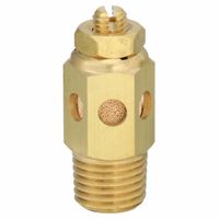
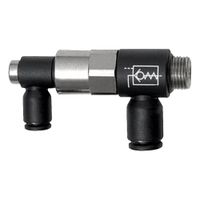
Exhaust Flow Controls
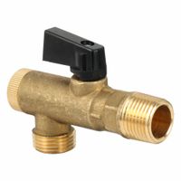
Filtered Ball Valves
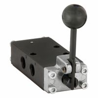
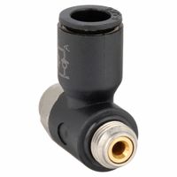
Inline Air Control Valves
Piloted Non-Return Valves
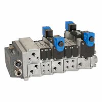
Pneumatic Directional Control Valve Systems, Fieldbus Modules & Accessories
Pneumatic Flow Control & Needle Valves
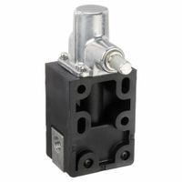
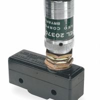
Pneumatic Limit Valves
Pneumatic Pressure Regulators
Pneumatic Shuttle Valves
Pneumatic Sleeve Valves
Sandwich Manifold Compressed Air Regulators
Vacuum & Pressure Relief Valves
Frequently Asked Questions
What are pneumatic valves and how do they work?
How do pneumatic directional control valves regulate airflow?
What are the different types of pneumatic valves and their functions?
How do electro-pneumatic actuators operate in a pneumatic system?
What is the role of pneumatic pressure regulators in a system?
How do pneumatic flow control and needle valves provide precise flow control?
What are the benefits of using piloted non-return valves in pneumatic systems?
How do vacuum and pressure relief valves ensure optimal system performance?
What are the applications of pneumatic limit valves and exhaust flow controls?
How do sandwich manifold compressed air regulators function in a pneumatic system?