Call +(254) 703 030 000 / 751 483 999 / 721 704 777
.....Read More
Frequently Asked Questions
What is weld testing and inspection?
Weld testing and inspection are critical processes in the field of welding to ensure the quality, safety, and reliability of welded structures and components. These processes involve various techniques and methods to evaluate the integrity and performance of welds.
Weld testing can be broadly categorized into destructive and non-destructive testing (NDT). Destructive testing involves physically breaking or altering the weld to assess its properties. Common methods include tensile testing, bend testing, and impact testing, which provide information on the weld's strength, ductility, and toughness.
Non-destructive testing, on the other hand, evaluates the weld without causing damage. NDT methods include visual inspection, radiographic testing (X-rays), ultrasonic testing, magnetic particle testing, and dye penetrant testing. These techniques help detect surface and subsurface defects such as cracks, porosity, and incomplete fusion.
Inspection is the process of examining welds to ensure they meet specified standards and codes. It involves visual inspection, where inspectors look for surface defects, and dimensional inspection, which checks the weld's size and shape against design specifications. Inspectors also verify that welding procedures, materials, and equipment comply with relevant standards.
Weld testing and inspection are essential for maintaining safety and quality in industries like construction, aerospace, automotive, and oil and gas. They help prevent failures that could lead to costly repairs, accidents, or even loss of life. By identifying defects and ensuring compliance with standards, these processes contribute to the longevity and performance of welded structures.
How does dye penetrant testing work?
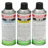
Dye penetrant testing (DPT) is a non-destructive testing method used to detect surface-breaking defects in non-porous materials. The process involves several key steps:
1. **Surface Preparation**: The test surface must be clean and free from contaminants like oil, grease, or dirt, which could obstruct the penetrant. Cleaning methods include solvents, alkaline cleaning, or mechanical cleaning.
2. **Application of Penetrant**: A liquid dye penetrant is applied to the surface. This penetrant is typically a bright-colored or fluorescent liquid that seeps into any surface-breaking defects through capillary action. The penetrant is allowed to dwell on the surface for a specified time to ensure it penetrates any flaws.
3. **Excess Penetrant Removal**: After the dwell time, excess penetrant is carefully removed from the surface. This is done using a cleaner or water, depending on the type of penetrant used (water-washable, solvent-removable, or post-emulsifiable). Care is taken to avoid removing penetrant from defects.
4. **Application of Developer**: A developer is applied to draw out the penetrant trapped in defects. The developer acts as a blotter, creating a visible indication of any flaws. Developers can be dry powder, water-based, or non-aqueous.
5. **Inspection**: The surface is inspected under appropriate lighting conditions. For visible dye penetrants, white light is used, while ultraviolet light is used for fluorescent penetrants. Indications of defects appear as colored or fluorescent marks on the surface.
6. **Post-Cleaning**: After inspection, the component is cleaned to remove any remaining developer and penetrant.
DPT is widely used for its simplicity, cost-effectiveness, and ability to detect fine surface defects in metals, plastics, ceramics, and other non-porous materials.
What are the benefits of magnetic particle testing?
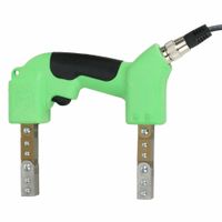
Magnetic particle testing (MPT) offers several benefits in non-destructive testing (NDT) for detecting surface and near-surface discontinuities in ferromagnetic materials.
1. **Sensitivity**: MPT is highly sensitive to small surface and slightly subsurface defects, such as cracks, seams, and inclusions, which might not be visible to the naked eye.
2. **Speed and Efficiency**: The process is relatively quick, allowing for rapid inspection of large areas or volumes, making it suitable for high-volume production environments.
3. **Cost-Effectiveness**: Compared to other NDT methods, MPT is generally less expensive, both in terms of equipment and operational costs, while still providing reliable results.
4. **Simplicity**: The technique is straightforward and does not require extensive training to perform basic inspections, although interpretation of results may require more expertise.
5. **Immediate Results**: MPT provides immediate visual indications of defects, allowing for quick decision-making regarding the integrity of the tested component.
6. **Versatility**: It can be applied to a wide range of shapes and sizes of ferromagnetic materials, including complex geometries, without the need for extensive preparation.
7. **Portability**: Portable equipment is available, enabling on-site inspections in various environments, including fieldwork and in-service inspections.
8. **Non-Destructive**: As an NDT method, MPT does not damage or alter the material being tested, preserving its usability and integrity.
9. **Enhanced Detection with Fluorescent Particles**: Using fluorescent magnetic particles under UV light can enhance the visibility of defects, improving detection accuracy.
10. **Compatibility with Other NDT Methods**: MPT can be used in conjunction with other NDT techniques to provide a comprehensive assessment of material integrity.
These benefits make magnetic particle testing a valuable tool in industries such as aerospace, automotive, and construction, where ensuring the integrity of critical components is essential.
How do weld inspection gauges ensure quality?
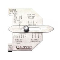
Weld inspection gauges are critical tools in ensuring the quality and integrity of welded joints. They provide precise measurements and assessments of various weld attributes, ensuring compliance with industry standards and specifications. Here's how they contribute to quality assurance:
1. **Dimensional Accuracy**: Weld inspection gauges measure critical dimensions such as weld size, throat thickness, and leg length. Ensuring these dimensions meet specified criteria is essential for the structural integrity and strength of the weld.
2. **Profile Assessment**: These gauges help in evaluating the weld profile, including concavity, convexity, and reinforcement. Proper profile ensures even stress distribution and prevents weaknesses that could lead to failure.
3. **Defect Detection**: Gauges can identify surface defects like undercuts, porosity, and misalignment. Detecting these defects early allows for corrective actions, preventing potential failures in service.
4. **Angle and Alignment Verification**: They measure angles and alignment of welds, ensuring that components are joined correctly. Misalignment can lead to stress concentrations and premature failure.
5. **Compliance with Standards**: Weld inspection gauges ensure that welds comply with relevant standards such as AWS, ASME, and ISO. Compliance is crucial for safety, reliability, and legal requirements.
6. **Repeatability and Consistency**: Using gauges provides consistent and repeatable measurements, reducing human error and ensuring uniform quality across multiple welds.
7. **Documentation and Traceability**: Gauges facilitate documentation of inspection results, providing traceability and accountability. This documentation is vital for quality control and audits.
By providing accurate, reliable, and consistent measurements, weld inspection gauges play a vital role in maintaining the quality and safety of welded structures, ultimately ensuring their performance and longevity.
What is the purpose of welding temperature indicators?
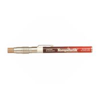
Welding temperature indicators are tools or materials used to ensure that the correct temperature is achieved and maintained during the welding process. Their primary purpose is to enhance the quality and integrity of the weld by providing a visual or measurable indication that the appropriate temperature has been reached. This is crucial because the temperature directly affects the metallurgical properties of the weld, including its strength, ductility, and resistance to corrosion.
These indicators help in several ways:
1. **Quality Assurance**: By confirming that the correct temperature is achieved, welding temperature indicators help ensure that the weld meets the required specifications and standards. This is vital for the structural integrity of the welded components.
2. **Process Control**: They allow welders to monitor and control the welding process in real-time, ensuring that the heat input is consistent and within the desired range. This helps in preventing defects such as cracking, warping, or incomplete fusion.
3. **Safety**: Maintaining the correct temperature reduces the risk of overheating, which can lead to hazardous conditions such as fires or equipment damage.
4. **Efficiency**: By providing immediate feedback, these indicators help in reducing the time spent on rework and repairs, thereby increasing productivity.
5. **Cost-effectiveness**: Proper temperature control minimizes material wastage and reduces the likelihood of costly failures or repairs.
Common types of welding temperature indicators include temperature-sensitive paints, crayons, and electronic devices like thermocouples and infrared thermometers. Each type has its specific applications and advantages, depending on the welding process and materials involved.
How do you perform a dye penetrant test?
To perform a dye penetrant test, follow these steps:
1. **Surface Preparation**: Clean the test surface thoroughly to remove dirt, grease, oil, and other contaminants. Use a suitable cleaner or solvent and ensure the surface is dry before proceeding.
2. **Application of Penetrant**: Apply the dye penetrant evenly over the test area. This can be done by spraying, brushing, or dipping. Allow the penetrant to dwell on the surface for the recommended time, typically 5 to 30 minutes, to enable it to seep into any surface-breaking defects.
3. **Excess Penetrant Removal**: After the dwell time, remove excess penetrant from the surface. Use a clean, lint-free cloth or absorbent paper and a suitable cleaner. Be careful not to remove penetrant from defects. For water-washable penetrants, rinse with water.
4. **Application of Developer**: Apply a thin, even layer of developer to the surface. The developer acts as a blotter, drawing penetrant out of defects to form visible indications. Allow the developer to dry for the specified time, usually 10 to 30 minutes.
5. **Inspection**: Inspect the surface under appropriate lighting conditions. For visible dye penetrants, use white light; for fluorescent penetrants, use ultraviolet (UV) light. Look for indications of defects, which will appear as colored or fluorescent lines or spots.
6. **Post-Cleaning**: After inspection, clean the test surface to remove all traces of developer and penetrant. This is important to prevent contamination and ensure the component is ready for service.
7. **Documentation**: Record the results, noting any defects found, their location, and size. This documentation is crucial for quality control and future reference.
Ensure all safety precautions and manufacturer instructions are followed throughout the process.
What materials can be tested with magnetic particle testing?
Magnetic particle testing (MPT) is a non-destructive testing method used to detect surface and near-surface discontinuities in ferromagnetic materials. These materials are those that can be magnetized to a significant degree. The primary materials that can be tested using MPT include:
1. **Iron**: As a fundamental ferromagnetic material, iron and its alloys are highly suitable for MPT. This includes both pure iron and various iron-based alloys.
2. **Carbon Steel**: Widely used in construction and manufacturing, carbon steel is one of the most common materials tested with MPT due to its ferromagnetic properties.
3. **Low Alloy Steel**: These steels, which contain small amounts of alloying elements, retain ferromagnetic properties and are suitable for MPT.
4. **Tool Steel**: Known for their hardness and resistance to abrasion, tool steels are also ferromagnetic and can be effectively tested using MPT.
5. **Cast Iron**: Despite its brittleness, cast iron is ferromagnetic and can be inspected using MPT to detect surface cracks and other discontinuities.
6. **Nickel and Nickel Alloys**: Some nickel alloys are ferromagnetic and can be tested with MPT, although the degree of magnetism can vary based on the specific alloy composition.
7. **Cobalt and Cobalt Alloys**: Similar to nickel, certain cobalt alloys exhibit ferromagnetic properties suitable for MPT.
Materials that are non-ferromagnetic, such as austenitic stainless steels, aluminum, copper, brass, and titanium, cannot be effectively tested using MPT because they do not retain significant magnetism. For these materials, other non-destructive testing methods like dye penetrant testing, ultrasonic testing, or eddy current testing are more appropriate.
What standards are used for weld inspection?
Weld inspection standards are crucial for ensuring the quality, safety, and reliability of welded structures. Key standards include:
1. **American Welding Society (AWS) Standards**: AWS D1.1 is one of the most widely used standards for structural welding, covering inspection criteria for steel structures. AWS D1.2, D1.3, and D1.6 cover aluminum, sheet steel, and stainless steel, respectively.
2. **American Society of Mechanical Engineers (ASME) Standards**: ASME Section IX provides guidelines for the qualification of welders and welding procedures. ASME Section V outlines nondestructive examination (NDE) methods, including radiographic and ultrasonic testing.
3. **International Organization for Standardization (ISO) Standards**: ISO 5817 specifies quality levels for imperfections in fusion-welded joints, while ISO 3834 provides comprehensive quality requirements for fusion welding of metallic materials.
4. **British Standards (BS EN)**: BS EN 1011 offers guidance on welding processes and associated inspection techniques. BS EN 970 and BS EN 1435 focus on visual and radiographic inspection methods, respectively.
5. **European Standards (EN)**: EN 1090 is essential for the execution of steel and aluminum structures, including inspection requirements. EN 12062 provides guidelines for NDE of welds.
6. **API Standards**: The American Petroleum Institute (API) 1104 standard is used for welding pipelines and related facilities, detailing inspection and testing procedures.
7. **Canadian Standards Association (CSA) Standards**: CSA W59 and CSA W47.1 are used in Canada for welding steel construction and certification of companies, respectively.
These standards encompass various inspection methods such as visual inspection, radiographic testing, ultrasonic testing, magnetic particle testing, and liquid penetrant testing, ensuring comprehensive evaluation of weld quality.
How do you measure weld quality?
Weld quality is measured through various methods to ensure structural integrity, safety, and performance. Key techniques include:
1. **Visual Inspection**: The simplest method, involving checking for surface defects like cracks, porosity, undercuts, and misalignment. It requires good lighting and sometimes magnification tools.
2. **Radiographic Testing (RT)**: Uses X-rays or gamma rays to detect internal flaws. It provides a permanent record and is effective for identifying voids, inclusions, and cracks.
3. **Ultrasonic Testing (UT)**: Employs high-frequency sound waves to detect internal defects. It is highly sensitive and can determine the depth and size of flaws.
4. **Magnetic Particle Testing (MT)**: Suitable for ferromagnetic materials, this method uses magnetic fields to reveal surface and near-surface discontinuities by attracting iron particles to defect areas.
5. **Dye Penetrant Testing (PT)**: Involves applying a liquid dye to the weld surface, which seeps into cracks and is then made visible with a developer. It is effective for detecting surface-breaking defects.
6. **Eddy Current Testing (ET)**: Utilizes electromagnetic induction to detect surface and near-surface defects, particularly in conductive materials.
7. **Destructive Testing**: Involves physically breaking the weld to examine its properties. Methods include tensile testing, bend testing, and impact testing to assess strength, ductility, and toughness.
8. **Metallographic Examination**: Analyzes the microstructure of the weld through sectioning and polishing, providing insights into grain structure and phase distribution.
9. **Hardness Testing**: Measures the resistance of the weld to deformation, indicating potential brittleness or softness.
10. **Code Compliance**: Ensures the weld meets industry standards and specifications, such as those from the American Welding Society (AWS) or the American Society of Mechanical Engineers (ASME).
These methods, often used in combination, provide a comprehensive assessment of weld quality.
What are common defects found in welds?
Common defects in welds include:
1. **Porosity**: Gas pockets or voids trapped in the weld metal, often caused by contamination or improper shielding gas.
2. **Inclusions**: Non-metallic materials, such as slag or oxides, trapped in the weld, usually due to inadequate cleaning or improper welding techniques.
3. **Cracks**: Fractures in the weld or heat-affected zone, which can be hot (occurring during solidification) or cold (occurring after solidification), often due to excessive stress or rapid cooling.
4. **Undercut**: A groove melted into the base metal adjacent to the weld toe, often caused by excessive welding speed or current.
5. **Lack of Fusion**: Incomplete joining of the weld metal and base metal or between weld passes, typically due to insufficient heat or improper technique.
6. **Incomplete Penetration**: Failure of the weld metal to extend through the joint thickness, often due to inadequate heat or improper joint preparation.
7. **Overlap**: Excess weld metal that rolls over the base metal without fusing, usually caused by excessive deposition or incorrect welding angle.
8. **Distortion**: Warping of the welded components due to uneven heating and cooling, often managed by proper welding sequence and fixturing.
9. **Spatter**: Small droplets of molten metal expelled from the weld, which can adhere to the surrounding surfaces, often due to excessive current or incorrect settings.
10. **Burn-through**: Excessive penetration that results in holes in the base metal, typically due to excessive heat input.
11. **Lamellar Tearing**: Cracks in the base metal parallel to the weld, often due to high restraint and poor material properties.
12. **Weld Profile Defects**: Irregularities in the shape of the weld bead, such as excessive convexity or concavity, often due to improper technique or settings.