Call +(254) 703 030 000 / 751 483 999 / 721 704 777
.....Read More
Frequently Asked Questions
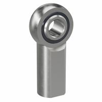
What are the main differences between spherical rod ends and fixed rod ends?
Spherical rod ends and fixed rod ends are both types of mechanical joints used to connect components, but they differ in design, functionality, and applications.
1. **Design and Structure**:
- **Spherical Rod Ends**: These have a spherical bearing inside a housing, allowing for angular movement. The inner ring rotates within the outer ring, providing a pivoting motion.
- **Fixed Rod Ends**: These are rigid and do not allow for angular movement. They typically consist of a solid rod with a threaded end for attachment.
2. **Movement and Flexibility**:
- **Spherical Rod Ends**: Offer multi-directional movement, accommodating misalignment and angular motion. They are ideal for applications requiring flexibility and movement in multiple planes.
- **Fixed Rod Ends**: Provide a stable, non-movable connection. They are used where precise alignment and rigidity are necessary.
3. **Applications**:
- **Spherical Rod Ends**: Commonly used in applications like automotive suspensions, aircraft control systems, and machinery where dynamic loads and misalignment occur.
- **Fixed Rod Ends**: Suitable for static applications where components need to be held in a fixed position, such as in structural frameworks or where precise alignment is critical.
4. **Load Handling**:
- **Spherical Rod Ends**: Can handle both radial and axial loads due to their design, making them versatile for dynamic applications.
- **Fixed Rod Ends**: Primarily handle axial loads and are not designed for accommodating angular misalignment.
5. **Installation and Maintenance**:
- **Spherical Rod Ends**: May require more maintenance due to moving parts and potential wear.
- **Fixed Rod Ends**: Generally require less maintenance due to their simple, static design.
In summary, spherical rod ends are chosen for their flexibility and ability to handle misalignment, while fixed rod ends are selected for their rigidity and precise alignment capabilities.
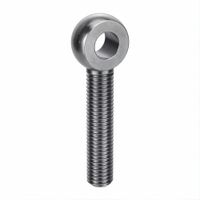
How do Heim joints work in power transmission systems?
Heim joints, also known as rod ends or spherical rod end bearings, are mechanical articulating joints used in power transmission systems to provide a flexible connection between components. They consist of a spherical ball with a hole through the center, encased in a cylindrical housing. This design allows for angular misalignment and rotational movement, making them ideal for applications where components need to pivot or move relative to each other.
In power transmission systems, Heim joints are typically used in linkages, control arms, and steering systems. They allow for the transmission of force while accommodating misalignment and movement, which is crucial in systems where components are subject to dynamic loads and varying angles. The spherical ball rotates within the housing, providing a pivot point that can handle both radial and axial loads.
Heim joints are often employed in automotive, aerospace, and industrial machinery applications. In automotive systems, for example, they are used in suspension and steering linkages to allow for smooth movement and precise control. In industrial machinery, they can be found in robotic arms and other equipment where precise movement and alignment are necessary.
The materials used for Heim joints vary depending on the application, with common choices including steel, stainless steel, and aluminum for the housing, and PTFE or nylon for the bearing surface to reduce friction and wear. Proper lubrication and maintenance are essential to ensure their longevity and performance.
Overall, Heim joints are critical components in power transmission systems, providing the necessary flexibility and movement while maintaining the integrity and efficiency of the system.
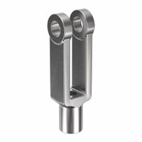
What are the applications of clevis and yoke ends in mechanical systems?
Clevis and yoke ends are critical components in mechanical systems, providing pivotal connections that allow for controlled movement and load transfer. Their applications are diverse and span across various industries:
1. **Automotive Industry**: Clevis and yoke ends are used in suspension systems, steering linkages, and brake systems to facilitate movement and absorb shocks. They ensure that components can pivot and align correctly, enhancing vehicle stability and handling.
2. **Aerospace**: In aircraft, these components are used in control systems, landing gear, and actuators. They provide reliable connections that can withstand high loads and vibrations, ensuring the safety and performance of the aircraft.
3. **Construction Machinery**: Heavy equipment like excavators and cranes use clevis and yoke ends in hydraulic cylinders and linkages. They allow for the articulation of arms and booms, enabling precise control and movement of heavy loads.
4. **Industrial Machinery**: In manufacturing, clevis and yoke ends are found in conveyor systems, robotic arms, and presses. They facilitate the movement and alignment of parts, contributing to efficient and accurate operations.
5. **Marine Applications**: Used in rigging and mooring systems, clevis and yoke ends provide secure connections that can withstand harsh marine environments. They are essential for the safe operation of ships and offshore platforms.
6. **Agricultural Equipment**: Tractors and harvesters use these components in their hydraulic systems and linkages to allow for the movement and control of attachments, improving the versatility and efficiency of the equipment.
7. **Railway Systems**: In trains, clevis and yoke ends are used in coupling systems and suspension components, ensuring smooth and safe operation by allowing for controlled movement and load distribution.
Overall, clevis and yoke ends are indispensable in mechanical systems where movement, alignment, and load transfer are critical, providing durability and reliability across various applications.
How do you select the right rod end for a specific application?
To select the right rod end for a specific application, consider the following factors:
1. **Load Requirements**: Determine the type and magnitude of loads (axial, radial, or combination) the rod end will encounter. Choose a rod end with an appropriate load rating to ensure durability and performance.
2. **Material**: Select materials based on environmental conditions and load requirements. Common materials include steel, stainless steel, and aluminum. For corrosive environments, stainless steel or coated materials are preferable.
3. **Type of Movement**: Identify the type of movement (oscillating, rotational, or linear) and select a rod end that accommodates the required motion without excessive wear.
4. **Misalignment**: Consider the degree of misalignment in the application. Choose a rod end with sufficient angular misalignment capability to prevent binding and ensure smooth operation.
5. **Thread Type and Size**: Ensure the rod end has the correct thread type (male or female) and size to fit the application. Verify compatibility with existing components.
6. **Operating Environment**: Assess environmental factors such as temperature, moisture, and exposure to chemicals. Select rod ends with appropriate seals or coatings to withstand these conditions.
7. **Maintenance Requirements**: Decide between maintenance-free or lubricated rod ends based on maintenance capabilities and application needs. Maintenance-free options are ideal for hard-to-reach areas.
8. **Cost and Availability**: Balance performance requirements with budget constraints. Consider the availability of the rod end for timely replacements or repairs.
9. **Industry Standards**: Ensure the rod end complies with relevant industry standards and certifications for safety and reliability.
10. **Supplier Reputation**: Choose a reputable supplier known for quality and support to ensure reliable performance and assistance when needed.
What materials are commonly used for manufacturing rod ends?
Rod ends, also known as heim joints or rose joints, are mechanical articulating joints used in various applications. The materials commonly used for manufacturing rod ends include:
1. **Steel**: Carbon steel and alloy steel are frequently used due to their strength and durability. They are often coated or plated with zinc, chrome, or nickel to enhance corrosion resistance.
2. **Stainless Steel**: Offers excellent corrosion resistance and is ideal for applications exposed to moisture or chemicals. It is commonly used in the food, pharmaceutical, and marine industries.
3. **Aluminum**: Lightweight and corrosion-resistant, aluminum rod ends are suitable for applications where weight reduction is crucial, such as in aerospace and automotive industries.
4. **Brass**: Known for its good corrosion resistance and machinability, brass is used in applications where electrical conductivity is also a factor.
5. **Bronze**: Offers good wear resistance and is often used in applications with high loads and low speeds. It is also resistant to corrosion and is self-lubricating.
6. **Plastic/Polymer**: Materials like nylon or PTFE are used for lightweight applications where corrosion resistance and low friction are important. They are suitable for environments where metal-to-metal contact is undesirable.
7. **Composite Materials**: These are used for specialized applications requiring specific properties like high strength-to-weight ratios or resistance to extreme temperatures.
Each material choice depends on the specific requirements of the application, including load capacity, environmental conditions, and cost considerations.
How do you install and maintain spherical rod ends?
To install spherical rod ends, first ensure you have the correct size and type for your application. Clean the mounting area to remove debris and contaminants. Align the rod end with the mounting hole, ensuring the ball is oriented correctly for the intended movement. Insert the rod end into the hole, and secure it using appropriate fasteners, such as bolts or nuts, ensuring they are tightened to the manufacturer's specified torque. If the rod end has a threaded shank, screw it into the mating component, using a locking nut to secure it in place. Ensure the rod end moves freely without binding.
For maintenance, regularly inspect the rod ends for signs of wear, corrosion, or damage. Check for excessive play or looseness, which may indicate wear. Lubricate the rod ends as recommended by the manufacturer, typically using a suitable grease or lubricant to ensure smooth operation and reduce friction. Clean the rod ends periodically to remove dirt and debris that can cause wear. Replace rod ends if they show signs of significant wear or damage to prevent failure. Ensure that all fasteners remain tight and secure during regular maintenance checks.
What are the advantages of using clevis ends in linkage systems?
Clevis ends offer several advantages in linkage systems:
1. **Versatility**: Clevis ends can be used in a wide range of applications, from automotive to industrial machinery, due to their adaptable design.
2. **Ease of Assembly and Disassembly**: The pin connection in clevis ends allows for quick assembly and disassembly, facilitating maintenance and repairs without the need for specialized tools.
3. **Adjustability**: Clevis ends can be easily adjusted to accommodate different lengths and angles, providing flexibility in design and application.
4. **Load Distribution**: They help in distributing loads evenly across the linkage system, reducing stress concentrations and enhancing the durability of the system.
5. **Alignment**: Clevis ends allow for slight misalignments in the linkage system, which can be crucial in dynamic applications where perfect alignment is difficult to maintain.
6. **Cost-Effectiveness**: Their simple design and ease of manufacturing make clevis ends a cost-effective solution for many linkage systems.
7. **Durability**: Made from robust materials, clevis ends can withstand significant mechanical stress and environmental conditions, ensuring long-term performance.
8. **Compact Design**: Their compact size allows for use in space-constrained environments without compromising functionality.
9. **Safety**: The secure pin connection minimizes the risk of accidental disconnection, enhancing the safety of the linkage system.
10. **Compatibility**: Clevis ends are compatible with various types of pins and rods, making them suitable for integration into existing systems.
These advantages make clevis ends a popular choice in designing efficient and reliable linkage systems.
How do you measure and specify the size of a rod end?
To measure and specify the size of a rod end, follow these steps:
1. **Thread Size**: Determine the thread size of the rod end. This is typically specified in either metric (e.g., M8, M10) or imperial (e.g., 1/4-20, 3/8-24) units. Use a thread gauge or calipers to measure the diameter and pitch of the threads.
2. **Bore Diameter**: Measure the bore diameter, which is the internal diameter of the hole in the spherical bearing. This is crucial for ensuring compatibility with the mating shaft or bolt.
3. **Ball Width**: Measure the width of the ball, which is the spherical part of the rod end. This dimension is important for understanding the load distribution and fit within the housing.
4. **Housing Width**: Measure the width of the housing, which is the outer casing that holds the spherical ball. This dimension affects the overall size and fit of the rod end in its application.
5. **Overall Length**: Measure the overall length from the end of the threads to the opposite end of the housing. This dimension is important for ensuring the rod end fits within the available space.
6. **Misalignment Angle**: Determine the maximum misalignment angle, which is the angle at which the rod end can pivot. This is important for applications requiring flexibility and movement.
7. **Load Ratings**: Check the manufacturer's specifications for static and dynamic load ratings. These values indicate the maximum loads the rod end can handle safely.
8. **Material and Finish**: Note the material (e.g., steel, stainless steel, aluminum) and any surface treatments or coatings (e.g., zinc plating) that affect durability and corrosion resistance.
By accurately measuring and specifying these dimensions and characteristics, you ensure the rod end will perform effectively in its intended application.
What are the common failure modes of rod ends and how can they be prevented?
Common failure modes of rod ends include:
1. **Wear and Tear**: Continuous movement causes surface degradation. Prevention involves regular lubrication and using materials with high wear resistance.
2. **Corrosion**: Exposure to moisture and chemicals leads to rust. Prevention includes using corrosion-resistant materials like stainless steel and applying protective coatings.
3. **Fatigue**: Repeated stress cycles cause cracks. Prevention involves proper material selection, ensuring correct load ratings, and avoiding overloading.
4. **Misalignment**: Incorrect installation or excessive angular movement causes stress. Prevention includes ensuring proper alignment during installation and using rod ends with higher misalignment capabilities.
5. **Overloading**: Exceeding load capacity leads to deformation or breakage. Prevention involves selecting rod ends with appropriate load ratings and regularly inspecting for signs of stress.
6. **Contamination**: Dirt and debris cause abrasion. Prevention includes using seals or boots to protect the joint and maintaining a clean environment.
7. **Improper Installation**: Incorrect assembly leads to premature failure. Prevention involves following manufacturer guidelines and ensuring proper torque specifications.
8. **Temperature Extremes**: High or low temperatures affect material properties. Prevention includes selecting materials suitable for the operating temperature range.
9. **Vibration**: Continuous vibration causes loosening or fatigue. Prevention involves using locking mechanisms and damping systems.
10. **Material Defects**: Flaws in manufacturing lead to weak points. Prevention includes quality control measures and selecting reputable suppliers.
Regular maintenance, proper installation, and choosing the right rod end for the application are crucial in preventing these failures.
How do rod ends contribute to the efficiency of power transmission systems?
Rod ends, also known as heim joints or rose joints, play a crucial role in enhancing the efficiency of power transmission systems by providing precise and flexible connections between components. These mechanical articulating joints allow for angular misalignment and rotational movement, which are essential in systems where components are subject to dynamic loads and varying angles.
1. **Alignment and Flexibility**: Rod ends accommodate misalignments between connected components, reducing stress and wear. This flexibility ensures that power is transmitted smoothly, minimizing energy losses due to friction or binding.
2. **Load Distribution**: By allowing for angular movement, rod ends help distribute loads more evenly across the system. This balanced load distribution reduces the risk of component failure and enhances the overall durability and reliability of the system.
3. **Vibration Dampening**: Rod ends can absorb and dampen vibrations, which are common in power transmission systems. This capability reduces noise and wear, contributing to a quieter and more efficient operation.
4. **Reduced Maintenance**: The design of rod ends often includes self-lubricating materials or easy access for lubrication, which decreases maintenance requirements and downtime. This ensures that the system operates efficiently over a longer period.
5. **Compact Design**: Rod ends offer a compact solution for connecting components, which is beneficial in systems where space is limited. Their design allows for efficient use of space without compromising performance.
6. **Versatility**: Available in various sizes and materials, rod ends can be tailored to specific applications, ensuring optimal performance under different environmental conditions and load requirements.
In summary, rod ends enhance the efficiency of power transmission systems by providing flexibility, reducing stress, dampening vibrations, and requiring minimal maintenance, all of which contribute to a more reliable and effective system.