.....Read More
Ball Bearing Mandrels
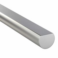
D-Profile Rotary Shafts
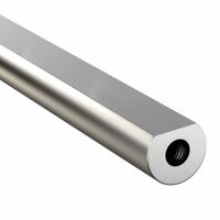
D-Profile Rotary Shafts with Tapped Hole
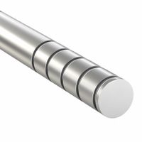
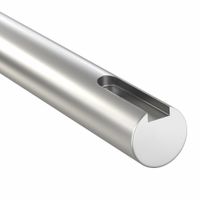
Grooved Rotary Shafts
Keyed Rotary Shafts
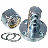
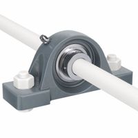
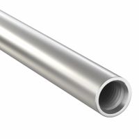
Mounts for Bearings & Rotary Components
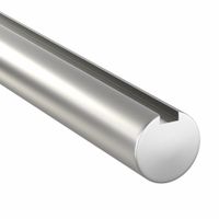
Partially D-Profile Rotary Shafts
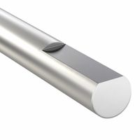
Partially Keyed Rotary Shafts
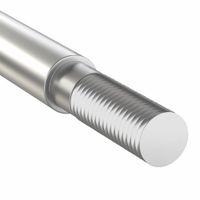
Partially Threaded Rotary Shafts
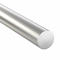
Round Rotary Shafts
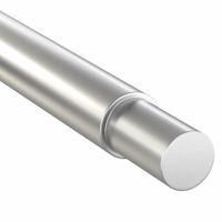
Stepped Rotary Shafts
Tapped Hole Rotary Shafts
Frequently Asked Questions
What is a rotary shaft used for?
How do you choose the right rotary shaft for an application?
What materials are rotary shafts typically made from?
How do you install a rotary shaft?
What are the differences between keyed and D-profile rotary shafts?
How do you maintain and lubricate a rotary shaft?
What are the common causes of rotary shaft failure?
How do you measure a rotary shaft for replacement?
What are the benefits of using a grooved rotary shaft?
How do you align a rotary shaft with other components?