Call +(254) 703 030 000 / 751 483 999 / 721 704 777
- Home
- Power Transmission
- Gearing
.....Read More
Frequently Asked Questions
What are the different types of gears and their applications?
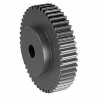
1. **Spur Gears**: These have straight teeth and are mounted on parallel shafts. They are used in applications requiring moderate speed and torque, such as clocks, washing machines, and conveyor systems.
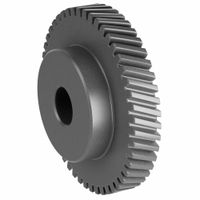
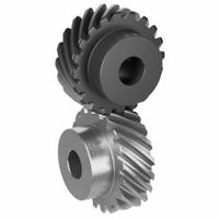
2. **Helical Gears**: Featuring angled teeth, these gears provide smoother and quieter operation than spur gears. They are used in automotive transmissions and other high-speed applications due to their ability to handle higher loads.
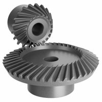
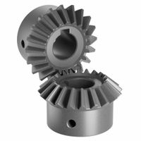
3. **Bevel Gears**: With conically shaped teeth, bevel gears are used to transmit motion between intersecting shafts, typically at a 90-degree angle. They are found in differential drives, hand drills, and printing presses.
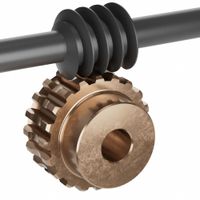
4. **Worm Gears**: Consisting of a worm (screw) and a worm wheel, these gears provide high reduction ratios and are used in applications requiring large speed reductions and torque multiplication, such as elevators and conveyor systems.
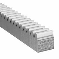
5. **Rack and Pinion Gears**: This system converts rotational motion into linear motion. It is commonly used in steering systems of cars and in railways for track switching.
6. **Planetary Gears**: Comprising a central sun gear, planet gears, and a ring gear, these are used in applications requiring high torque density and compact size, such as automatic transmissions and electric screwdrivers.
7. **Hypoid Gears**: Similar to bevel gears but with axes that do not intersect, hypoid gears are used in automotive differentials to provide smooth and quiet operation.
8. **Spiral Bevel Gears**: These have curved teeth and are used in applications requiring high-speed and high-torque transmission, such as in aircraft engines and marine applications.
9. **Herringbone Gears**: A double helical gear with no gap between the two helical faces, used in heavy machinery to handle high torque and reduce axial thrust.
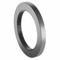
10. **Internal Gears**: These have teeth on the inside of a cylinder and are used in planetary gear systems and gear couplings.
How do gears transfer rotational motion and power?
Gears transfer rotational motion and power through the interlocking of their teeth. When one gear, known as the driver, rotates, its teeth engage with the teeth of another gear, called the driven gear. This engagement causes the driven gear to rotate. The transfer of motion and power depends on the size and number of teeth on each gear, which determines the gear ratio.
The gear ratio is the ratio of the number of teeth on the driven gear to the number of teeth on the driver gear. This ratio affects the speed and torque of the output. If the driven gear has more teeth than the driver gear, the output speed decreases, but the torque increases, which is useful for applications requiring more force. Conversely, if the driven gear has fewer teeth, the output speed increases, but the torque decreases, suitable for applications needing higher speed.
Gears can be arranged in various configurations, such as spur, helical, bevel, and worm gears, each serving different purposes. Spur gears have straight teeth and are used for parallel shafts, while helical gears have angled teeth for smoother and quieter operation. Bevel gears are used for intersecting shafts, and worm gears provide high torque reduction in compact spaces.
The efficiency of power transfer depends on the precision of gear manufacturing and the lubrication used to reduce friction and wear. Proper alignment and maintenance are crucial to ensure effective power transmission and longevity of the gear system. Overall, gears are fundamental components in machinery, enabling the controlled transfer of motion and power across various mechanical systems.
What is the difference between spur gears and helical gears?
Spur gears and helical gears are both types of cylindrical gears used to transmit motion and power between parallel shafts, but they differ in design, operation, and application.
Spur gears have straight teeth that are parallel to the gear's axis. This design allows them to transmit power efficiently and is easy to manufacture, making them cost-effective. However, the straight teeth engage abruptly, causing noise and stress, especially at high speeds. This can lead to increased wear and tear. Spur gears are typically used in applications where noise control is not critical, such as in simple machinery and low-speed applications.
Helical gears, on the other hand, have teeth that are cut at an angle to the gear's axis, forming a helix. This angled design allows for gradual engagement of the teeth, resulting in smoother and quieter operation compared to spur gears. The angled teeth also allow for greater load capacity and efficiency, as more teeth are in contact during operation. However, helical gears generate axial thrust, which requires additional bearings to handle the thrust load. They are more complex to manufacture and thus more expensive. Helical gears are commonly used in automotive transmissions and other high-speed, high-load applications where noise reduction and smooth operation are important.
In summary, the main differences between spur and helical gears lie in their tooth design, noise levels, load capacity, and manufacturing complexity. Spur gears are simpler and cheaper but noisier, while helical gears offer smoother, quieter operation at a higher cost and complexity.
How do bevel gears change the direction of motion?
Bevel gears change the direction of motion by utilizing their unique design, which features conically shaped teeth that are cut on an angular surface. These gears are typically mounted on shafts that are positioned at an angle to each other, most commonly at 90 degrees, although other angles are possible. When one bevel gear, known as the driver, is rotated, its teeth engage with the teeth of the second gear, known as the driven gear. This engagement transfers the rotational motion from the driver to the driven gear.
The key to changing the direction of motion lies in the orientation of the gear shafts. As the driver gear rotates, the angular arrangement of the teeth causes the driven gear to rotate in a different plane. For example, if the driver gear is mounted on a horizontal shaft, the driven gear, mounted on a vertical shaft, will rotate in a vertical plane. This change in the plane of rotation effectively alters the direction of motion.
The angle between the shafts, known as the shaft angle, determines the specific direction change. In most applications, bevel gears are used to achieve a 90-degree change in direction, but they can be designed for other angles as needed. The precision of the gear teeth and the alignment of the shafts are crucial for efficient power transmission and minimal wear.
Bevel gears are commonly used in various mechanical systems, such as automotive differentials, where they allow the wheels to rotate at different speeds while changing the direction of power flow from the driveshaft to the wheels. Their ability to change the direction of motion while maintaining smooth and efficient power transmission makes them essential components in many engineering applications.
What are the advantages of using worm gears?
Worm gears offer several advantages that make them suitable for specific applications:
1. **High Reduction Ratios**: Worm gears can achieve high reduction ratios in a single gear set, which is beneficial for applications requiring significant speed reduction and increased torque.
2. **Compact Design**: The design of worm gears allows for a compact setup, as they can provide high reduction ratios without the need for multiple gear stages, saving space in machinery.
3. **Self-Locking Capability**: Due to the angle of the worm, worm gears can have a self-locking feature, preventing the gear from back-driving. This is useful in applications like lifts or hoists where reverse motion needs to be prevented.
4. **Smooth and Quiet Operation**: The sliding contact between the worm and the gear results in smooth and quiet operation, making worm gears suitable for applications where noise reduction is important.
5. **Shock Load Absorption**: Worm gears can absorb shock loads better than other gear types due to their design, which distributes the load over a larger area.
6. **High Torque Output**: The design of worm gears allows them to transmit high torque, which is advantageous in heavy-duty applications.
7. **Versatility in Mounting**: Worm gears can be mounted in various orientations, providing flexibility in design and installation.
8. **Durability and Reliability**: Made from robust materials, worm gears are durable and reliable, offering long service life with proper maintenance.
These advantages make worm gears ideal for applications such as conveyor systems, elevators, automotive steering mechanisms, and industrial machinery where high torque, compact design, and reliability are essential.
How do gear racks convert rotary motion into linear motion?
A gear rack is a linear or flat toothed component that works in conjunction with a pinion, which is a small cylindrical gear. The conversion of rotary motion into linear motion using a gear rack and pinion system occurs through the interaction of their teeth.
When the pinion rotates, its teeth engage with the teeth on the gear rack. As the pinion turns, it pushes or pulls the gear rack in a straight line. The direction of the linear motion depends on the direction of the pinion's rotation. If the pinion rotates clockwise, the gear rack moves in one direction, and if it rotates counterclockwise, the gear rack moves in the opposite direction.
The distance the gear rack moves linearly is determined by the number of rotations of the pinion and the pitch of the teeth on both the pinion and the rack. The pitch is the distance between corresponding points on adjacent teeth. A finer pitch results in smoother motion but requires more rotations for the same linear distance, while a coarser pitch results in faster linear movement with fewer rotations.
The gear rack and pinion system is efficient for converting rotary motion to linear motion because it provides precise control over the movement, can handle high loads, and offers a straightforward mechanical design. This system is commonly used in applications such as steering mechanisms in vehicles, CNC machinery, and various types of automation equipment.
What is the function of miter gears in mechanical systems?
Miter gears are a type of bevel gear specifically designed to transmit rotational motion between intersecting shafts at a 90-degree angle. They are characterized by their equal number of teeth and identical pitch angles, typically set at 45 degrees, which allows them to operate in pairs with a 1:1 gear ratio. This means that the input and output shafts rotate at the same speed, making miter gears ideal for applications where the direction of rotation needs to be changed without altering the speed or torque.
The primary function of miter gears in mechanical systems is to facilitate the smooth transfer of power between perpendicular shafts. This is particularly useful in machinery where space constraints or design requirements necessitate a change in the direction of the drive. Miter gears are commonly used in various applications, including automotive differentials, hand drills, and conveyor systems, where they help in redirecting motion efficiently.
Additionally, miter gears can be used to split power between two shafts, allowing for the distribution of mechanical energy to multiple components within a system. This capability is essential in complex machinery where synchronized operation of different parts is required.
Miter gears are typically made from durable materials such as steel, brass, or plastic, depending on the application's load and environmental conditions. Their design ensures minimal friction and wear, contributing to the longevity and reliability of the mechanical system.
In summary, miter gears play a crucial role in mechanical systems by enabling the change of rotational direction between intersecting shafts, maintaining speed consistency, and distributing power efficiently, all while ensuring smooth and reliable operation.
How do internal gears work in planetary gearsets?
In a planetary gearset, internal gears play a crucial role in the transmission of power and torque. The planetary gearset consists of three main components: the sun gear, the planet gears, and the ring gear, which is the internal gear. The ring gear is a large gear with teeth on its inner circumference, encircling the planet gears.
The planet gears are mounted on a carrier and mesh with both the sun gear and the ring gear. As the sun gear rotates, it drives the planet gears, which in turn roll along the inside of the ring gear. This configuration allows for multiple gear ratios and the distribution of torque among the components.
The internal gear, or ring gear, can be held stationary, driven, or used as the output, depending on the desired gear ratio and direction of rotation. When the ring gear is held stationary, the sun gear drives the planet gears, causing the planet carrier to rotate, which results in a reduction in speed and an increase in torque. If the sun gear is held stationary and the ring gear is driven, the planet carrier rotates in the opposite direction, providing a different gear ratio. When the planet carrier is held stationary, the sun gear and ring gear rotate in opposite directions, offering yet another gear ratio.
The internal gear's design allows for compactness and efficiency, as the planetary gearset can achieve high torque output in a relatively small space. This makes planetary gearsets with internal gears ideal for applications in automatic transmissions, robotics, and other machinery requiring precise and efficient power transmission.
What are the common materials used for manufacturing gears?
Common materials used for manufacturing gears include:
1. **Steel**: Widely used due to its strength, durability, and ability to withstand high loads. Types include carbon steel, alloy steel, and stainless steel. Heat treatment processes like carburizing and nitriding enhance hardness and wear resistance.
2. **Cast Iron**: Known for good wear resistance and vibration damping properties. It is cost-effective and used in applications where noise reduction is important.
3. **Brass and Bronze**: These non-ferrous metals offer good corrosion resistance and are used in applications requiring low friction and smooth operation, such as in marine environments.
4. **Aluminum**: Lightweight and corrosion-resistant, aluminum gears are used in applications where weight reduction is crucial, though they are not suitable for high-load applications.
5. **Plastics**: Materials like nylon, acetal, and polycarbonate are used for gears in low-load applications. They offer advantages like low noise, corrosion resistance, and reduced weight.
6. **Powdered Metal**: Used for producing gears with complex shapes and fine details. This method allows for cost-effective mass production and can include materials like iron, steel, and copper alloys.
7. **Composites**: Advanced composite materials are used for specialized applications requiring high strength-to-weight ratios and resistance to environmental factors.
Each material is selected based on factors like load capacity, environmental conditions, cost, and specific application requirements.
How do ratchet gears and pawls prevent backward rotation?
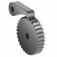
Ratchet gears and pawls work together to allow rotational movement in one direction while preventing it in the opposite direction. A ratchet gear is a wheel with teeth cut into its edge, and a pawl is a lever or catch that engages with these teeth.
When the ratchet gear rotates in the allowed direction, the pawl slides over the sloped side of the teeth, typically aided by a spring mechanism that keeps the pawl pressed against the gear. This sliding action is smooth because the pawl is designed to easily ride up and over the sloped side of each tooth. As the gear continues to rotate, the pawl drops into the space between the teeth, ready to engage the next tooth.
If an attempt is made to rotate the gear in the opposite direction, the pawl immediately engages with the vertical side of a tooth. This engagement prevents backward movement because the pawl is unable to slide over the vertical face of the tooth. The force applied in the reverse direction only serves to press the pawl more firmly against the tooth, effectively locking the gear in place.
The effectiveness of this mechanism depends on the precise design of the teeth and the pawl. The angle and shape of the teeth, the material of the components, and the tension of the spring all contribute to the reliability of the ratchet and pawl system. This mechanism is widely used in applications like socket wrenches, winches, and clocks, where controlled, unidirectional movement is essential.
