Call +(254) 703 030 000 / 751 483 999 / 721 704 777
.....Read More
Frequently Asked Questions
What are the different types of bushings used in rotating drive shafts?
1. **Plain Bushings**: These are the simplest type, made from materials like bronze, brass, or plastic. They provide a low-friction interface between the shaft and housing, suitable for low-speed applications.
2. **Flanged Bushings**: Similar to plain bushings but with a flange at one end. The flange helps in axial positioning and can handle some axial loads, making them ideal for applications where axial movement needs to be restricted.
3. **Sleeve Bushings**: Cylindrical in shape, these bushings are used for linear or rotational movements. They are often made from materials like bronze or composite materials for enhanced wear resistance.
4. **Spherical Bushings**: These allow for angular misalignment between the shaft and housing. They are used in applications where the shaft may not be perfectly aligned with the housing, providing flexibility and reducing stress.
5. **Thrust Bushings**: Designed to handle axial loads, these bushings are used in applications where the shaft experiences significant axial forces. They are often made from materials that can withstand high pressure and wear.
6. **Split Bushings**: These are designed in two halves, making them easy to install and replace without disassembling the entire assembly. They are used in applications where maintenance and replacement are frequent.
7. **Composite Bushings**: Made from a combination of materials like PTFE, fiberglass, and resin, these bushings offer low friction, high wear resistance, and can operate without lubrication, suitable for high-load and high-speed applications.
8. **Hydrodynamic Bushings**: These use a thin film of lubricant to support the shaft, reducing friction and wear. They are used in high-speed applications where minimal friction is critical.
9. **Magnetic Bushings**: Utilize magnetic fields to support the shaft, eliminating physical contact and reducing wear. They are used in precision applications where minimal friction and wear are essential.
How do you install a quick detachable bushing?
1. **Select the Correct Bushing**: Ensure you have the right size and type of quick detachable (QD) bushing for your application.
2. **Prepare the Shaft and Hub**: Clean the shaft and the bore of the hub to remove any dirt, oil, or debris. This ensures a secure fit.
3. **Align the Bushing**: Insert the bushing into the hub. Align the holes in the bushing with the holes in the hub.
4. **Insert the Bolts**: Insert the bolts through the holes in the hub and into the threaded holes in the bushing. Do not tighten them yet.
5. **Position the Assembly on the Shaft**: Slide the hub and bushing assembly onto the shaft to the desired position. Ensure the keyway is aligned if a key is used.
6. **Tighten the Bolts**: Gradually tighten the bolts in a crisscross pattern to ensure even pressure. Use a torque wrench to tighten the bolts to the manufacturer's specified torque.
7. **Check Alignment**: Ensure the assembly is properly aligned on the shaft. Adjust if necessary.
8. **Secure the Key (if applicable)**: If a key is used, ensure it is properly seated in the keyway.
9. **Final Torque Check**: Recheck the torque on the bolts to ensure they are tightened to the correct specification.
10. **Inspect the Installation**: Verify that the bushing is securely installed and that there is no movement between the bushing and the hub or shaft.
11. **Test the Assembly**: Run the machinery at low speed to ensure the bushing is properly installed and there is no wobble or misalignment.
12. **Regular Maintenance**: Periodically check the bushing for wear and re-torque the bolts as necessary to maintain a secure fit.
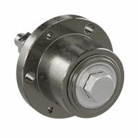
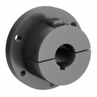
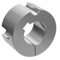
What is the purpose of a split taper bushing?
A split taper bushing is a mechanical component used to securely mount a rotating element, such as a pulley, sprocket, or gear, onto a shaft. Its primary purpose is to provide a reliable and precise connection between the shaft and the mounted component, ensuring efficient power transmission and alignment.
The split taper bushing is designed with a tapered outer surface and a split along its length. This design allows the bushing to be compressed and expanded, facilitating easy installation and removal. When the bushing is installed, it is inserted into the bore of the component and then tightened using screws. As the screws are tightened, the bushing is drawn into the tapered bore, causing it to contract around the shaft. This contraction creates a tight, frictional grip on the shaft, preventing slippage and ensuring that the component remains securely in place during operation.
The split design also allows for easy removal and replacement of the bushing without the need for special tools or excessive force. This feature is particularly beneficial in maintenance and repair scenarios, where quick and efficient disassembly is required.
Additionally, split taper bushings help in accommodating slight misalignments and variations in shaft size, providing a degree of flexibility in applications where precision alignment is challenging. They are available in various sizes and materials, making them suitable for a wide range of industrial applications.
Overall, the purpose of a split taper bushing is to enhance the reliability, efficiency, and ease of maintenance of mechanical systems by providing a secure and adaptable method for mounting rotating components onto shafts.
How do you install a taper lock bushing?
1. **Preparation**: Ensure the shaft and bushing surfaces are clean and free from any burrs or debris. Verify that the bushing and hub are compatible.
2. **Positioning**: Slide the bushing onto the shaft without the key in place. Align the bushing's keyway with the shaft keyway, then insert the key.
3. **Aligning**: Place the hub over the bushing, ensuring the holes in the hub align with the threaded holes in the bushing.
4. **Inserting Bolts**: Insert the bolts through the hub and into the bushing's threaded holes. Do not fully tighten them yet.
5. **Initial Tightening**: Gradually tighten the bolts in a crisscross pattern to ensure even pressure. This will draw the bushing into the hub, creating a tight fit.
6. **Final Tightening**: Use a torque wrench to tighten the bolts to the manufacturer's specified torque value. This ensures the bushing is securely seated.
7. **Checking Alignment**: Ensure the assembly is properly aligned and that the bushing is flush with the hub.
8. **Securing**: If applicable, install any set screws to further secure the bushing in place.
9. **Inspection**: Double-check all components for proper installation and alignment. Ensure there is no movement between the bushing and the hub.
10. **Operation**: Once installed, the assembly is ready for operation. Regularly inspect the bushing for wear and re-tighten bolts as necessary.
11. **Removal (if needed)**: To remove, loosen the bolts and insert them into the removal holes. Tighten them evenly to push the bushing out of the hub.
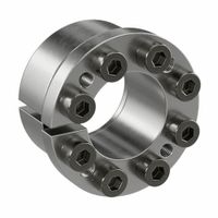
What are the advantages of keyless bushings?
Keyless bushings offer several advantages:
1. **Ease of Installation and Removal**: Keyless bushings are designed for quick and simple installation and removal, reducing downtime and labor costs. They do not require keyways, which simplifies the assembly process.
2. **Elimination of Backlash**: These bushings provide a secure, frictional connection between the shaft and the hub, eliminating backlash and ensuring precise positioning. This is particularly beneficial in applications requiring high accuracy and repeatability.
3. **Uniform Stress Distribution**: The design of keyless bushings allows for even distribution of stress along the shaft and hub, reducing the risk of stress concentrations that can lead to component failure.
4. **High Torque Transmission**: Keyless bushings can transmit high torque without slipping, making them suitable for heavy-duty applications. The frictional connection provides a strong grip, enhancing performance.
5. **Versatility**: They are compatible with a wide range of shaft sizes and can be used in various applications, from light to heavy machinery. This versatility makes them a preferred choice in many industries.
6. **Reduced Wear and Tear**: By eliminating the need for keyways, keyless bushings reduce wear and tear on the shaft and hub, extending the lifespan of the components and reducing maintenance costs.
7. **Improved Balance**: The absence of keyways and the uniform clamping force help maintain balance in rotating assemblies, reducing vibration and noise.
8. **Corrosion Resistance**: Many keyless bushings are made from materials that resist corrosion, enhancing their durability and performance in harsh environments.
9. **Cost-Effective**: Although the initial cost may be higher, the reduction in maintenance, downtime, and component wear can lead to overall cost savings.
10. **Flexibility in Design**: They allow for more flexibility in design, as they do not require precise alignment of keyways, enabling more innovative engineering solutions.
How do idler bushings function in conveyor systems?
Idler bushings in conveyor systems serve as critical components that facilitate the smooth and efficient operation of the conveyor belt. They are typically used in conjunction with idler rollers, which support the conveyor belt and the material being transported. The primary function of idler bushings is to reduce friction and wear between the rotating idler rollers and their mounting shafts, ensuring that the rollers can spin freely and with minimal resistance.
Idler bushings are usually made from materials with low friction coefficients, such as nylon, polyurethane, or other engineered plastics. These materials are chosen for their durability, resistance to wear, and ability to operate effectively in various environmental conditions, including exposure to dust, moisture, and temperature fluctuations.
By minimizing friction, idler bushings help to reduce the energy consumption of the conveyor system, as less power is required to move the belt and its load. This efficiency contributes to lower operational costs and extends the lifespan of the conveyor components by reducing the mechanical stress on the system.
Additionally, idler bushings play a role in noise reduction. By providing a smooth interface between the roller and the shaft, they help to dampen vibrations and reduce the noise generated by the conveyor system, which is particularly beneficial in environments where noise levels are a concern.
Overall, idler bushings are essential for maintaining the reliability and efficiency of conveyor systems, ensuring that they operate smoothly, with reduced maintenance requirements and extended service life.
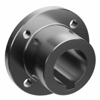
What is the installation process for weld-on bushing hubs?
1. **Preparation**: Ensure all necessary tools and safety equipment are available. Clean the shaft and hub surfaces to remove any dirt, grease, or rust. Verify the bushing and hub sizes match the shaft specifications.
2. **Positioning**: Slide the bushing onto the shaft. Align the keyway on the bushing with the key on the shaft if applicable. Position the hub over the bushing, ensuring the hub's flange is facing the correct direction.
3. **Alignment**: Align the hub and bushing assembly to the desired position on the shaft. Ensure the hub is centered and perpendicular to the shaft axis. Use a straight edge or dial indicator to check alignment.
4. **Tack Welding**: Secure the hub in place by tack welding at several points around the hub's circumference. This prevents movement during the final welding process.
5. **Final Welding**: Weld the hub to the bushing using an appropriate welding technique (e.g., MIG, TIG, or stick welding). Follow the manufacturer's specifications for weld size and type. Weld in a circular pattern to ensure even distribution of heat and stress.
6. **Cooling**: Allow the assembly to cool naturally. Avoid rapid cooling methods like water quenching, which can cause material stress or distortion.
7. **Inspection**: Inspect the welds for any defects such as cracks or incomplete fusion. Use non-destructive testing methods if necessary to ensure weld integrity.
8. **Final Checks**: Verify the alignment and positioning of the hub on the shaft. Ensure the assembly rotates smoothly without binding or excessive play.
9. **Secure Fasteners**: If applicable, tighten any set screws or fasteners to secure the bushing to the shaft. Follow the recommended torque specifications.
10. **Testing**: Conduct a test run to ensure the assembly functions correctly under operational conditions. Make any necessary adjustments.
How do you choose the right bushing for a specific application?
To choose the right bushing for a specific application, consider the following factors:
1. **Load Capacity**: Determine the load the bushing will support. Choose a bushing material and design that can handle the maximum load without deforming or failing.
2. **Material Compatibility**: Select a bushing material compatible with the shaft and housing materials to prevent galvanic corrosion and ensure longevity. Common materials include bronze, plastic, and composite.
3. **Operating Environment**: Consider the environment where the bushing will operate. For high-temperature applications, use materials like bronze or high-temperature plastics. For corrosive environments, consider stainless steel or corrosion-resistant composites.
4. **Lubrication Requirements**: Decide if the application requires self-lubricating bushings or if regular maintenance is feasible. Self-lubricating bushings, such as those made from PTFE or oil-impregnated bronze, are ideal for maintenance-free applications.
5. **Speed and Motion Type**: Assess the speed and type of motion (rotational, oscillating, or linear). High-speed applications may require low-friction materials, while oscillating motions might benefit from materials with good wear resistance.
6. **Dimensional Constraints**: Ensure the bushing fits within the available space and meets the dimensional tolerances of the application. Custom sizes may be necessary for unique applications.
7. **Cost and Availability**: Balance the cost of the bushing with its performance benefits. Consider readily available options to minimize lead times.
8. **Installation and Maintenance**: Evaluate the ease of installation and maintenance. Some bushings require special tools or techniques for installation.
9. **Regulatory and Safety Standards**: Ensure the bushing complies with relevant industry standards and safety regulations.
By carefully considering these factors, you can select a bushing that optimally meets the demands of your specific application.
What are the common issues faced during bushing installation?
Common issues faced during bushing installation include:
1. **Misalignment**: Incorrect alignment can lead to uneven load distribution, causing premature wear or failure.
2. **Improper Fit**: Bushings that are too tight or too loose can result in operational inefficiencies or damage. A tight fit may cause deformation, while a loose fit can lead to excessive movement.
3. **Contamination**: Dirt, dust, or other contaminants can enter the bushing during installation, leading to increased friction and wear.
4. **Inadequate Lubrication**: Insufficient lubrication can cause increased friction, leading to overheating and accelerated wear.
5. **Incorrect Material Selection**: Using the wrong material for the bushing can result in poor performance, especially under specific environmental or load conditions.
6. **Overheating**: Excessive heat during installation, often due to improper handling or fitting techniques, can damage the bushing material.
7. **Tooling Issues**: Using incorrect or worn-out tools can damage the bushing or the housing, leading to improper installation.
8. **Surface Finish Problems**: Poor surface finish on the housing or shaft can lead to improper seating and increased wear.
9. **Thermal Expansion**: Failure to account for thermal expansion can result in improper fit and function, especially in high-temperature applications.
10. **Installation Force**: Applying excessive force during installation can deform the bushing or the housing, leading to operational issues.
11. **Lack of Pre-Installation Inspection**: Failing to inspect components before installation can result in overlooking defects or damage.
12. **Environmental Factors**: Exposure to moisture, chemicals, or extreme temperatures during installation can affect bushing performance.
Addressing these issues requires careful planning, proper tool selection, adherence to manufacturer guidelines, and thorough inspection before and after installation.
How do bushings help in reducing vibration and extending the life of shafts?
Bushings, also known as plain bearings, play a crucial role in reducing vibration and extending the life of shafts by providing a smooth interface between moving parts. They are typically made from materials like rubber, polyurethane, or metal, which can absorb and dampen vibrations. This damping effect minimizes the transmission of vibrations from the shaft to other components, reducing noise and wear.
By providing a low-friction surface, bushings facilitate smooth rotational or linear movement of the shaft. This reduces the mechanical stress and heat generated during operation, which can otherwise lead to premature wear and failure of the shaft and associated components. The reduction in friction also means less energy is lost in the form of heat, improving the overall efficiency of the system.
Bushings also help in maintaining the alignment of the shaft. Misalignment can lead to uneven load distribution, causing excessive wear and tear. By ensuring proper alignment, bushings distribute loads evenly across the shaft, reducing localized stress concentrations that can lead to fatigue and failure.
Furthermore, bushings can accommodate slight misalignments and shaft deflections, which are common in dynamic systems. This flexibility prevents the transmission of excessive forces to the shaft, thereby protecting it from damage.
In summary, bushings reduce vibration and extend the life of shafts by providing damping, reducing friction, maintaining alignment, and accommodating misalignments. These functions collectively enhance the durability and performance of mechanical systems, leading to longer service life and reduced maintenance costs.