Call +(254) 703 030 000 / 751 483 999 / 721 704 777
.....Read More
Frequently Asked Questions
What is the function of a motor starter?
A motor starter is an electrical device used to start, stop, and protect an electric motor. Its primary functions include: * **Starting the motor:** It provides the initial current required to get the motor running.
* **Stopping the motor:** It safely disconnects power to the motor, either through manual operation or automatic controls.
* **Overload protection:** It senses excessive current draw, which can damage the motor, and trips to shut off power, preventing overheating and burnout.
* **Short-circuit protection:** In some cases, it can also provide protection against short circuits.
* **Under-voltage protection:** It can prevent the motor from operating when the voltage is too low, which can also be damaging.
* **Reversing direction (in some models):** Certain motor starters allow for easy reversal of the motor's rotation direction.In essence, a motor starter acts as a control and safety device, ensuring the efficient and protected operation of electric motors in various industrial and commercial applications.
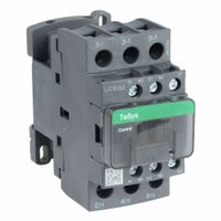
How do contactors work in motor control systems?
Contactors are essential components in motor control systems, acting as electrically controlled switches that make or break a power circuit. Their primary function is to safely and efficiently control the flow of electrical current to motors, enabling them to start, stop, and operate as required.
At their core, contactors consist of a coil, a set of contacts (both fixed and movable), and an electromagnet. When an electrical current is applied to the coil, it generates a magnetic field that energizes the electromagnet. This energized electromagnet then pulls the movable contacts towards the fixed contacts, closing the circuit and allowing current to flow to the motor. When the current to the coil is interrupted, the magnetic field collapses, and a spring typically forces the movable contacts back to their open position, breaking the circuit and stopping the motor.
Contactors are preferred over general-purpose relays for motor control due to their ability to handle higher current loads and their robust construction, which is designed to withstand the inductive loads associated with motors. They often include arc chutes to safely extinguish the electrical arc that forms when the contacts open and close, preventing damage and extending the contactor's lifespan.
In motor control systems, contactors are typically integrated with other components such as overload relays (to protect the motor from excessive current), control circuits (for starting and stopping operations), and sometimes variable frequency drives (for speed control). The precise operation of the contactor ensures that the motor receives power only when intended, contributing to the safety, efficiency, and longevity of the entire system.
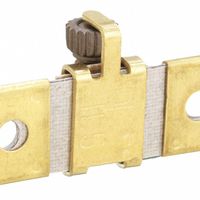
What is the purpose of an overload relay in motor starters?
An overload relay in motor starters is a crucial protective device designed to safeguard electric motors from damage caused by excessive current draw. Its primary purpose is to detect conditions where the motor is operating beyond its rated capacity, which can lead to overheating and ultimately, motor failure. When the current flowing through the motor exceeds a predetermined safe limit for a specific duration, the overload relay trips, opening the motor's power circuit and shutting it down. This prevents the motor windings from overheating, preserving the motor's lifespan and preventing costly repairs or replacements. Overload relays are adjustable, allowing them to be set to the specific full-load current of the motor they are protecting, ensuring precise and effective protection. They are essential for maintaining the operational integrity and longevity of industrial and commercial motors.
How can I regulate the speed of an electric motor?
Regulating the speed of an electric motor can be achieved through various methods, depending on the type of motor (AC or DC) and the application's specific requirements.
For DC motors, speed control is typically accomplished by varying the armature voltage or the field current. Increasing the armature voltage generally increases motor speed, while decreasing it reduces speed. Field weakening, achieved by reducing the field current, can also increase speed, though it reduces torque. Pulse Width Modulation (PWM) is a common electronic method used to effectively vary the average voltage supplied to the motor, offering precise control and efficiency.
For AC motors, especially induction motors, speed control is more complex but widely achieved using Variable Frequency Drives (VFDs) or Variable Speed Drives (VSDs). These devices control both the voltage and frequency of the power supplied to the motor. By increasing the frequency, the motor speed increases, and vice versa. VFDs are highly efficient and offer excellent control over a wide range of speeds. Other methods for AC motors include pole changing (for multi-speed motors) and slip control, though VFDs are the most prevalent in modern applications due to their versatility and energy savings.
The choice of method depends on factors such as cost, efficiency, required speed range, and torque characteristics.
What are the common methods to change the rotation direction of a motor?
Changing the rotation direction of a motor, often referred to as "reversing," depends on the type of motor.
For DC (Direct Current) motors, the most common method is to reverse the polarity of the voltage applied to the motor terminals. This means swapping the positive and negative connections. For brushed DC motors, this reverses the current flow through the armature, thereby reversing the direction of the magnetic field and consequently the rotation. For brushless DC (BLDC) motors, reversing the sequence of energizing the motor's phases (often controlled by an electronic speed controller or driver) will change the direction.
For AC (Alternating Current) motors, the methods vary by motor type: * **Single-Phase Induction Motors:** Reversing the direction of single-phase induction motors typically involves changing the connection of the starting winding relative to the main winding. This alters the phase relationship between the currents in these windings, which in turn changes the direction of the rotating magnetic field. This is often achieved by reversing the connections to the start winding through a switch or relay. Some single-phase motors (like shaded-pole motors) are generally not reversible or require significant modifications.
* **Three-Phase Induction Motors:** Reversing the direction of a three-phase induction motor is simpler. It's done by swapping any two of the three phase connections. This reverses the phase sequence of the applied voltage, causing the rotating magnetic field to rotate in the opposite direction, and the rotor follows.In all cases, proper safety precautions and understanding of the motor's wiring diagram are crucial before attempting to change its rotation direction.
How do motor monitoring and management systems enhance motor performance?
Motor monitoring and management systems enhance motor performance through several key mechanisms. Firstly, they provide real-time data on critical operating parameters such as temperature, vibration, current, and voltage. This continuous monitoring allows for early detection of anomalies or deviations from normal operating conditions. For example, an increase in vibration could indicate bearing wear, while elevated temperatures might point to inadequate cooling or excessive load.
Secondly, these systems often incorporate predictive analytics. By analyzing historical data and identifying trends, they can forecast potential equipment failures before they occur. This enables proactive maintenance scheduling, minimizing unexpected downtime and optimizing the lifespan of the motor. Instead of reactive repairs after a breakdown, maintenance can be planned during scheduled downtimes, reducing production losses.
Thirdly, motor management systems facilitate optimization of motor operation. They can help identify inefficiencies, such as motors running under partial load or experiencing excessive energy consumption. By providing insights into energy usage, these systems support strategies for energy efficiency, leading to reduced operational costs and a smaller carbon footprint. Some advanced systems can even adjust motor parameters dynamically to optimize performance based on changing load conditions.
Finally, these systems improve safety by alerting operators to hazardous conditions. For instance, an immediate shutdown can be triggered if a motor reaches critical temperature thresholds, preventing damage to the equipment or potential safety hazards. This comprehensive approach to monitoring, predictive maintenance, optimization, and safety ultimately leads to more reliable, efficient, and longer-lasting motor performance.
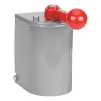
What are the differences between drum switches and motor switches?
Drum switches and motor switches both control electric motors, but they differ in their design, function, and typical applications.
A drum switch is a manually operated, multi-position switch primarily used for reversing the direction of rotation of a single-phase or three-phase AC motor. It typically has a rotating drum contact mechanism that allows for different wiring configurations to change the motor's polarity or phase sequence. Drum switches are often found in older machinery or applications where simple, direct motor reversal is required, such as hoists, machine tools, and conveyors. They are characterized by their robust, mechanical feel and limited number of operating positions (e.g., forward, off, reverse).
A motor switch, more broadly, refers to any switch designed to control a motor, including starting, stopping, and sometimes speed control or overload protection. This category encompasses a wide range of devices, from simple on/off toggle switches for small motors to complex motor starters for industrial applications. Motor starters, a common type of motor switch, often include contactors (for switching power), overload relays (for protection against excessive current), and control circuitry. Unlike drum switches, motor switches are not inherently designed for reversing motor direction as their primary function, though they can be incorporated into motor control circuits that do provide reversal.
In essence, a drum switch is a specific type of motor switch with a specialized function (motor reversal), while the term "motor switch" is a general category that includes a variety of devices for motor control, often with more advanced features and safety mechanisms.
How do you troubleshoot a faulty motor starter?
Troubleshooting a faulty motor starter involves a systematic approach to identify the root cause of the problem. Begin by checking for obvious issues like loose connections, burnt wires, or tripped circuit breakers. Next, verify the power supply to the starter, ensuring proper voltage and phase. Examine the overload relays for any signs of tripping or damage. If the motor is not starting, test the control circuit components such as the start/stop buttons, auxiliary contacts, and control transformer for continuity.
If the starter is chattering or failing to hold in, investigate issues with the coil, such as low voltage, open circuits, or shorted turns. Inspect the main contacts for pitting, burning, or signs of wear, as these can impede proper current flow. Utilize a multimeter to check for continuity across the contacts when the starter is energized.
Consider the motor itself. Issues with the motor, such as winding faults or bearing problems, can sometimes manifest as starter issues due to excessive current draw. Finally, consult the motor starter's wiring diagram and troubleshooting guide, as they provide specific instructions and common fault codes for the particular model. Always ensure safety precautions are followed, including de-energizing the circuit before performing any inspections or repairs.
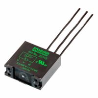
What are the benefits of using EMC suppressors in motor control systems?
EMC suppressors in motor control systems offer several key benefits. They primarily reduce electromagnetic interference (EMI), which can disrupt sensitive electronic equipment and compromise system reliability. By attenuating high-frequency noise generated by motors and power electronics, suppressors ensure stable operation of control systems, sensors, and communication networks. This prevention of interference leads to improved system performance and reduced downtime. Additionally, EMC suppressors help systems comply with regulatory standards for electromagnetic compatibility, preventing costly fines and ensuring market access. They can also extend the lifespan of components by protecting them from voltage spikes and transient overvoltages, ultimately enhancing the robustness and longevity of the motor control system.
How do you select the right contactor for a specific motor application?
Selecting the right contactor for a motor application involves considering several critical factors to ensure efficient and safe operation. First, the motor's full-load current (FLA) is paramount; the contactor's continuous current rating must exceed the motor's FLA by at least 15-25% to handle starting currents and potential overloads. Second, the motor's voltage rating must match the contactor's coil voltage. Third, the motor's horsepower (HP) or kilowatt (kW) rating is essential, as contactors are often rated by these values for specific voltage levels.
Additionally, the application's duty cycle—how frequently the motor starts and stops—influences the contactor's operational life. Heavy-duty applications require contactors designed for more frequent switching. The type of load (resistive, inductive, or capacitive) also plays a role, with inductive loads like motors typically requiring contactors with appropriate arc suppression capabilities. Environmental conditions, such as temperature, humidity, and the presence of dust or corrosive agents, necessitate contactors with suitable enclosures and materials for durability.
Finally, consider auxiliary contacts for control circuitry, such as interlocking or signaling, and any specific industry standards or certifications (e.g., UL, IEC) that the application demands. Overload protection, often integrated with or mounted alongside the contactor, is crucial for motor protection against sustained overcurrents. By carefully evaluating these factors, one can select a contactor that provides reliable performance and adequate protection for the motor application.