.....Read More

Frequently Asked Questions

What are instrumentation and control cables used for?

Instrumentation and control cables are specialized types of cables used primarily in industrial settings to transmit signals and control processes. These cables are essential for the accurate and efficient operation of automated systems. Instrumentation cables are designed to carry low-energy electrical signals used for monitoring and controlling electrical systems and processes. They are typically used to connect instruments and transmit data from sensors to control systems. These cables ensure that the data is transmitted with minimal interference and signal loss, which is crucial for maintaining the accuracy and reliability of the measurements. They are often shielded to protect against electromagnetic interference (EMI) and radio frequency interference (RFI), which can distort the signals. Control cables, on the other hand, are used to transmit control signals to various devices within an industrial setup. These cables are responsible for carrying signals that control the operation of equipment, such as starting or stopping motors, opening or closing valves, and other similar functions. Control cables are designed to handle higher voltages and currents compared to instrumentation cables, as they often need to power the devices they control. Both types of cables are used in a wide range of industries, including oil and gas, manufacturing, power generation, and chemical processing. They are crucial for ensuring the safe and efficient operation of complex systems by providing reliable communication between different components. Proper selection and installation of these cables are vital to prevent system failures and ensure operational efficiency.

What are the key differences between instrumentation cables and control cables?

Instrumentation cables and control cables are both used in industrial settings, but they serve different purposes and have distinct characteristics: 1. **Purpose**: - **Instrumentation Cables**: These are used to transmit low-energy electrical signals for monitoring and controlling electrical systems. They are crucial for precise data transmission in measurement and control applications. - **Control Cables**: These are used to transmit signals to control the functioning of equipment. They are designed to carry control signals to regulate the operation of machinery and systems. 2. **Signal Type**: - **Instrumentation Cables**: Typically carry low-voltage signals and are used for data transmission. They are designed to minimize interference and ensure accurate signal transmission. - **Control Cables**: Carry higher voltage signals compared to instrumentation cables and are used to control the operation of equipment. 3. **Construction**: - **Instrumentation Cables**: Often have more shielding to protect against electromagnetic interference (EMI) and radio frequency interference (RFI), ensuring signal integrity. - **Control Cables**: May have less shielding compared to instrumentation cables, as they are less sensitive to interference. 4. **Insulation and Shielding**: - **Instrumentation Cables**: Typically have superior insulation and shielding to protect against interference and ensure accurate data transmission. - **Control Cables**: Insulation is designed to withstand higher voltages and environmental conditions, but may not be as focused on shielding against interference. 5. **Applications**: - **Instrumentation Cables**: Used in process control, automation, and instrumentation systems where precise data transmission is critical. - **Control Cables**: Used in industrial automation, machinery, and equipment control systems where robust signal transmission is required. 6. **Flexibility**: - **Instrumentation Cables**: Generally more flexible to accommodate complex routing in instrumentation systems. - **Control Cables**: May be less flexible due to thicker insulation and construction designed for durability.

How do you select the right instrumentation and control cable for a specific application?

To select the right instrumentation and control cable for a specific application, consider the following factors: 1. **Application Requirements**: Determine the specific needs of the application, including the type of signals (analog or digital), voltage levels, and current requirements. 2. **Environmental Conditions**: Assess the environment where the cable will be installed. Consider temperature extremes, exposure to chemicals, moisture, UV radiation, and mechanical stresses. 
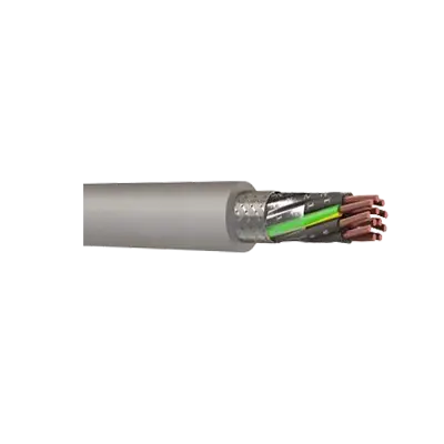
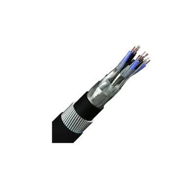
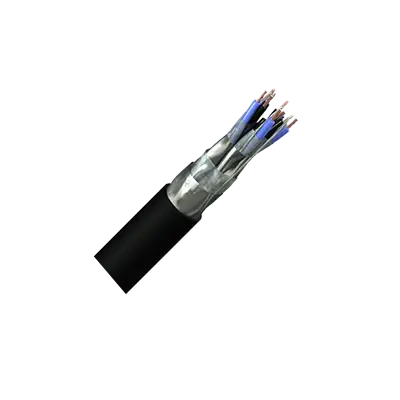
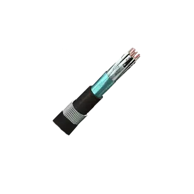
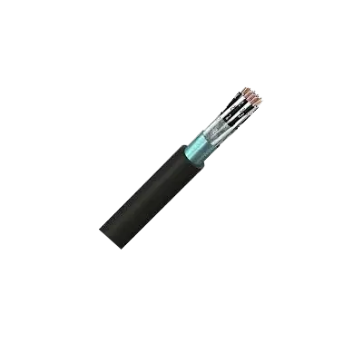
3. **Cable Type**: Choose between twisted pair, coaxial, or multi-conductor cables based on signal type and interference susceptibility. Twisted pair cables are ideal for minimizing electromagnetic interference (EMI). 
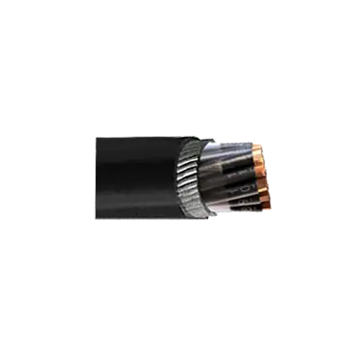
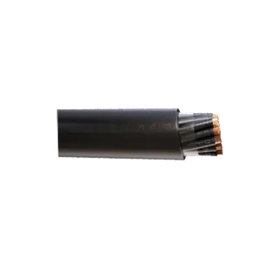
4. **Shielding**: Select appropriate shielding (e.g., foil, braid, or combination) to protect against EMI and radio frequency interference (RFI). The level of shielding depends on the interference level in the environment. 5. **Insulation Material**: Choose insulation based on temperature range, chemical resistance, and flexibility. Common materials include PVC, XLPE, and Teflon. 6. **Cable Size and Length**: Determine the appropriate gauge size to minimize voltage drop and ensure signal integrity over the required distance. Consider the maximum allowable length to prevent signal degradation. 7. **Standards and Certifications**: Ensure the cable meets relevant industry standards and certifications, such as UL, CSA, or IEC, for safety and performance. 8. **Installation Considerations**: Consider the installation method (e.g., conduit, tray, or direct burial) and ensure the cable is suitable for the chosen method. 9. **Cost and Availability**: Balance performance requirements with budget constraints and ensure the selected cable is readily available. 10. **Future Expansion**: Consider potential future needs for additional capacity or functionality to avoid costly upgrades. By evaluating these factors, you can select the most suitable instrumentation and control cable for your specific application.

What are the common materials used in the construction of instrumentation and control cables?

Instrumentation and control cables are essential for transmitting signals and data in various industrial applications. The common materials used in their construction include: 1. **Conductors**: Typically made from copper due to its excellent electrical conductivity. Copper can be used in solid or stranded form, with stranded being more flexible. In some cases, tinned copper is used for better corrosion resistance. 2. **Insulation**: Materials like PVC (Polyvinyl Chloride), PE (Polyethylene), XLPE (Cross-linked Polyethylene), and Teflon (PTFE) are commonly used. These materials provide electrical insulation and protect the conductors from environmental factors. 3. **Shielding**: To prevent electromagnetic interference (EMI), shielding is crucial. Common materials include aluminum foil, copper braid, or a combination of both. Aluminum foil provides 100% coverage, while copper braid offers flexibility and mechanical strength. 4. **Jacket**: The outer jacket protects the cable from physical damage and environmental conditions. PVC is widely used for its durability and cost-effectiveness. Other materials like LSZH (Low Smoke Zero Halogen) and PUR (Polyurethane) are used for specific applications requiring low smoke emission or high abrasion resistance. 5. **Filler Materials**: Used to maintain the cable's shape and provide additional mechanical strength. Common fillers include cotton, jute, or synthetic fibers. 6. **Armoring**: For enhanced mechanical protection, especially in harsh environments, steel wire or tape armoring is used. This is common in cables that are buried underground or exposed to potential physical damage. These materials are selected based on the specific requirements of the application, such as temperature range, flexibility, resistance to chemicals, and environmental conditions.

How do shielding and insulation affect the performance of instrumentation and control cables?

Shielding and insulation are critical components that significantly influence the performance of instrumentation and control cables. Shielding primarily serves to protect cables from electromagnetic interference (EMI) and radio frequency interference (RFI). These interferences can distort the signals transmitted through the cables, leading to inaccurate data transmission and potential malfunction of control systems. Shielding is typically made from materials like aluminum foil, copper braid, or a combination of both. It acts as a barrier, reflecting or absorbing unwanted external noise. This ensures that the signal integrity is maintained, which is crucial for precise control and instrumentation applications. Additionally, shielding can also prevent the cable from emitting interference that could affect nearby electronic equipment. Insulation, on the other hand, provides electrical isolation between the conductors within the cable and from external environments. It is made from materials such as PVC, polyethylene, or Teflon, which are chosen based on their dielectric properties, temperature resistance, and mechanical strength. Insulation prevents short circuits and protects the cable from environmental factors like moisture, chemicals, and physical damage. It also helps in maintaining the cable's flexibility and durability, which is essential for installations in dynamic or harsh environments. Together, shielding and insulation enhance the reliability and longevity of instrumentation and control cables. They ensure accurate signal transmission by minimizing interference and protecting against environmental and mechanical stresses. This is vital for maintaining the efficiency and safety of industrial processes, where precise control and monitoring are required.

What are the standards and certifications for instrumentation and control cables?

Instrumentation and control cables are subject to various standards and certifications to ensure safety, reliability, and performance. Key standards include: 1. **IEC Standards**: The International Electrotechnical Commission (IEC) provides global standards such as IEC 60092 for shipboard cables and IEC 60332 for flame retardant cables. 2. **IEEE Standards**: The Institute of Electrical and Electronics Engineers (IEEE) offers standards like IEEE 45 for marine applications and IEEE 383 for cable fire testing. 3. **UL Standards**: Underwriters Laboratories (UL) certifies cables for safety in the U.S., with standards like UL 13 for power-limited circuit cables and UL 2250 for instrumentation tray cables. 4. **NEC**: The National Electrical Code (NEC) in the U.S. provides guidelines for safe electrical design, including Article 725 for Class 1, 2, and 3 remote-control, signaling, and power-limited circuits. 5. **BS Standards**: British Standards (BS) such as BS 5308 specify requirements for instrumentation cables used in industrial applications. 6. **CSA Standards**: The Canadian Standards Association (CSA) provides standards like CSA C22.2 No. 239 for control and instrumentation cables. 7. **ISO Standards**: The International Organization for Standardization (ISO) offers standards like ISO 9001 for quality management systems, applicable to cable manufacturing processes. 8. **RoHS Compliance**: Restriction of Hazardous Substances (RoHS) compliance ensures cables are free from hazardous materials like lead and mercury. 9. **ATEX Certification**: For cables used in explosive atmospheres, ATEX certification ensures compliance with European safety standards. 10. **CE Marking**: Indicates conformity with health, safety, and environmental protection standards for products sold within the European Economic Area. These standards and certifications ensure that instrumentation and control cables meet necessary safety, environmental, and performance criteria for various applications.

How do you install and maintain instrumentation and control cables to ensure optimal performance?

To install and maintain instrumentation and control cables for optimal performance, follow these steps: 1. **Planning and Design**: Begin with a detailed plan and design, considering cable type, length, and routing. Ensure compliance with relevant standards and regulations. 2. **Cable Selection**: Choose cables with appropriate specifications for the environment, such as temperature, humidity, and chemical exposure. Consider shielded cables to minimize electromagnetic interference. 3. **Routing and Segregation**: Route cables away from power cables to reduce interference. Use separate trays or conduits for different types of signals (analog, digital, power). 4. **Installation**: - Use proper tools and techniques to avoid damaging the cables. - Maintain minimum bend radius as specified by the manufacturer. - Secure cables with appropriate clamps and ties to prevent movement and stress. 5. **Grounding and Shielding**: Properly ground and shield cables to protect against electrical noise. Connect shields at one end only to prevent ground loops. 6. **Testing and Commissioning**: After installation, test cables for continuity, insulation resistance, and signal integrity. Use appropriate testing equipment to ensure all connections are secure and functioning. 7. **Documentation**: Keep detailed records of cable types, routes, and connections for future reference and maintenance. 8. **Regular Inspection and Maintenance**: - Conduct periodic inspections to check for physical damage, corrosion, or wear. - Test cable performance regularly to detect any degradation. - Replace damaged or degraded cables promptly to prevent system failures. 9. **Environmental Considerations**: Protect cables from environmental factors such as moisture, heat, and mechanical stress using appropriate enclosures or conduits. 10. **Training and Safety**: Ensure personnel are trained in safe handling and maintenance practices to prevent accidents and ensure system reliability.