Call +(254) 703 030 000 / 751 483 999 / 721 704 777
.....Read More

Frequently Asked Questions
What are the main components of a pneumatic system?
A pneumatic system primarily consists of the following components:
1. **Compressor**: This is the heart of the pneumatic system, responsible for compressing air to the required pressure. It converts mechanical energy into pneumatic energy.
2. **Reservoir/Tank**: This component stores compressed air, ensuring a steady supply and helping to maintain consistent pressure levels within the system.
3. **Valves**: Valves control the flow and direction of the compressed air. Common types include directional control valves, pressure control valves, and flow control valves.
4. **Actuators**: These convert the energy of compressed air into mechanical motion. The most common types are pneumatic cylinders (linear actuators) and air motors (rotary actuators).
5. **Piping and Hoses**: These transport compressed air from the compressor to various components of the system. They must be durable and capable of withstanding high pressure.
6. **Filters**: Filters remove contaminants such as dust, oil, and moisture from the compressed air, ensuring the system operates efficiently and prolonging the life of components.
7. **Regulators**: These devices maintain the desired pressure level within the system by adjusting the air pressure to the required level for specific applications.
8. **Lubricators**: Lubricators add a fine mist of oil into the air stream to lubricate internal moving parts of pneumatic components, reducing wear and tear.
9. **Fittings and Connectors**: These are used to connect various components of the system, ensuring airtight seals and efficient air flow.
10. **Sensors and Gauges**: These monitor system parameters such as pressure, flow rate, and temperature, providing feedback for system control and maintenance.
Each component plays a crucial role in ensuring the efficient and reliable operation of a pneumatic system.
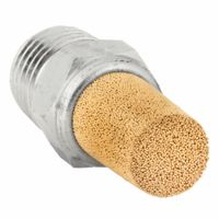
How do exhaust breather vents, mufflers, and silencers work in a pneumatic system?
Exhaust breather vents, mufflers, and silencers are components used in pneumatic systems to manage the release of compressed air, reduce noise, and protect the system from contaminants.
Exhaust breather vents allow air to escape from pneumatic components, such as cylinders or valves, while preventing the ingress of dirt and debris. They typically consist of a porous material that filters out contaminants, ensuring clean air discharge and maintaining system integrity.
Mufflers are designed to reduce the noise generated by the rapid release of compressed air. They work by dissipating the energy of the escaping air through a series of chambers or baffles, which slow down the air flow and reduce its velocity. This process decreases the sound intensity, making the operation of pneumatic systems quieter and more environmentally friendly.
Silencers function similarly to mufflers but are often more advanced in design. They not only reduce noise but also control the back pressure in the system, which can affect the performance of pneumatic components. Silencers use a combination of sound-absorbing materials and complex internal structures to minimize noise while maintaining optimal air flow. They are particularly useful in applications where noise reduction is critical, such as in manufacturing plants or urban environments.
Together, these components enhance the efficiency and safety of pneumatic systems by ensuring smooth air discharge, reducing noise pollution, and protecting against environmental contaminants.
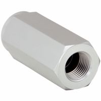
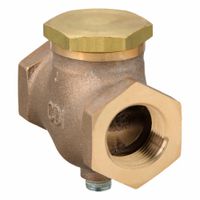
What is the function of a pneumatic check valve?
A pneumatic check valve is a type of valve used in pneumatic systems to allow airflow in one direction while preventing it from flowing in the opposite direction. Its primary function is to ensure unidirectional flow, which is crucial for maintaining the proper operation and safety of pneumatic systems.
The valve typically consists of a body, an inlet and outlet port, and a movable component such as a ball, disc, or poppet that acts as a barrier to reverse flow. When air flows in the desired direction, the pressure pushes the movable component away from the seat, allowing air to pass through. If the flow attempts to reverse, the pressure differential causes the component to seal against the seat, blocking the reverse flow.
Pneumatic check valves are essential in applications where backflow could cause damage or inefficiency, such as in air compressors, pneumatic actuators, and various industrial machinery. They help maintain pressure, prevent contamination, and protect equipment from potential damage due to reverse flow. Additionally, they can be used to isolate sections of a system for maintenance or to ensure that pressure is maintained in critical parts of the system even if the supply is interrupted.
Overall, the pneumatic check valve is a simple yet vital component that enhances the reliability and efficiency of pneumatic systems by ensuring that air flows in the intended direction only.
How do air fuses enhance the safety of a pneumatic system?
Air fuses enhance the safety of a pneumatic system by acting as a protective device that prevents uncontrolled release of compressed air in the event of a sudden line break or significant leak. They are designed to automatically shut off the air flow when it exceeds a predetermined rate, which is indicative of a failure in the system. This rapid response helps in several ways:
1. **Prevention of Equipment Damage**: By stopping the flow of air, air fuses prevent the over-pressurization of downstream components, which could otherwise lead to equipment damage or failure.
2. **Protection of Personnel**: In the event of a line rupture, the sudden release of high-pressure air can pose serious risks to personnel, including injury from flying debris or the force of the air itself. Air fuses mitigate this risk by quickly cutting off the air supply.
3. **Minimization of Downtime**: By isolating the problem area, air fuses allow the rest of the system to continue operating normally, reducing downtime and maintaining productivity while repairs are made.
4. **Energy Efficiency**: Preventing air loss through leaks or breaks helps maintain system efficiency, reducing energy consumption and operational costs.
5. **System Integrity**: Air fuses help maintain the integrity of the pneumatic system by ensuring that only the affected section is isolated, allowing for targeted maintenance and reducing the risk of further damage.
Overall, air fuses are a critical safety component in pneumatic systems, providing a reliable means of protecting both equipment and personnel from the hazards associated with high-pressure air systems.
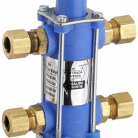
What is the purpose of air and liquid bypass valves in compressed air systems?
Air and liquid bypass valves in compressed air systems serve several critical functions to ensure efficient and safe operation.
1. **Pressure Regulation**: Bypass valves help maintain optimal pressure levels within the system. By redirecting excess air or liquid, they prevent over-pressurization, which can lead to equipment damage or system failure.
2. **Flow Control**: These valves manage the flow of air or liquid, ensuring that the system operates smoothly. They can redirect flow to different parts of the system as needed, maintaining balance and efficiency.
3. **System Protection**: Bypass valves act as safety mechanisms. In the event of a blockage or failure in the main line, they provide an alternate path for air or liquid, preventing pressure build-up and potential damage.
4. **Energy Efficiency**: By optimizing flow and pressure, bypass valves contribute to energy savings. They reduce the workload on compressors and pumps, leading to lower energy consumption and operational costs.
5. **Temperature Control**: In systems where temperature is a concern, bypass valves can help regulate it by controlling the flow of cooling or heating fluids, ensuring that components operate within safe temperature ranges.
6. **Maintenance and Servicing**: Bypass valves allow for sections of the system to be isolated for maintenance without shutting down the entire system. This ensures continuous operation and reduces downtime.
7. **System Flexibility**: They provide flexibility in system design and operation, allowing for adjustments and modifications without major overhauls.
Overall, air and liquid bypass valves are essential for maintaining the reliability, efficiency, and safety of compressed air systems.
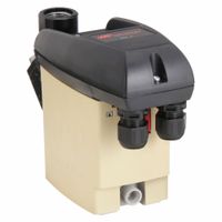
How do zero-loss condensate drains operate without losing pressure?
Zero-loss condensate drains operate by using a mechanism that allows them to discharge condensate without releasing compressed air, thus maintaining system pressure. These drains typically use a level-sensing mechanism, such as a float or electronic sensor, to detect the presence of condensate. When the condensate reaches a certain level, a valve opens to discharge it. The key to zero-loss operation is the use of a valve that opens only when necessary and closes before any compressed air can escape.
The process begins with the accumulation of condensate in a reservoir or chamber. A float or electronic sensor monitors the liquid level. Once the condensate reaches a predetermined level, the sensor triggers the opening of a discharge valve. This valve is often a solenoid or pneumatically operated valve that opens quickly to allow the condensate to exit.
The discharge path is designed to minimize air loss. Some systems use a diaphragm or piston mechanism that creates a seal, ensuring that only liquid is expelled. The valve closes immediately after the condensate is discharged, preventing any compressed air from escaping. This rapid open-and-close action is crucial for maintaining system pressure.
Additionally, some zero-loss drains incorporate a small reservoir or buffer chamber that temporarily holds the condensate, allowing for controlled discharge. This design further reduces the risk of air loss by ensuring that the valve only opens when there is sufficient condensate to be expelled.
Overall, zero-loss condensate drains are engineered to efficiently remove condensate while preserving the energy and pressure of the compressed air system, leading to improved efficiency and reduced operational costs.
What is the difference between float operated drain valves and air-operated drain valves?
Float-operated drain valves and air-operated drain valves are both used to remove condensate from compressed air systems, but they operate differently.
Float-Operated Drain Valves:
1. **Mechanism**: These valves use a float mechanism to detect the level of condensate. As the condensate level rises, the float lifts, eventually triggering the valve to open and discharge the accumulated liquid.
2. **Operation**: They operate automatically based on the liquid level, requiring no external power source.
3. **Applications**: Ideal for systems where electricity is not available or where simplicity and reliability are prioritized.
4. **Maintenance**: Generally low maintenance, but the float mechanism can be susceptible to dirt and debris, which may cause malfunction.
5. **Cost**: Typically less expensive due to their simple design and lack of electrical components.
Air-Operated Drain Valves:
1. **Mechanism**: These valves use compressed air to actuate the valve mechanism. They often incorporate a timer or sensor to control the opening and closing of the valve.
2. **Operation**: Can be programmed to open at specific intervals or in response to sensor input, providing more control over the drainage process.
3. **Applications**: Suitable for systems requiring precise control over condensate removal, often used in larger or more complex systems.
4. **Maintenance**: Requires regular maintenance to ensure the timer or sensor functions correctly. More components mean a higher potential for failure.
5. **Cost**: Generally more expensive due to the complexity and additional components like timers or sensors.
In summary, float-operated valves are simpler and more cost-effective, while air-operated valves offer greater control and are better suited for complex systems.
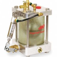
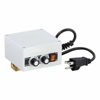
How do timed electric drain valves function in a compressed air system?
Timed electric drain valves in a compressed air system function by automatically removing accumulated condensate from the system at preset intervals. These valves are crucial for maintaining system efficiency and preventing damage caused by moisture.
The operation begins with the timer, which is set to open the valve at specific intervals. The timer can be adjusted to suit the system's needs, typically ranging from seconds to hours, depending on the volume of condensate produced. When the timer activates, it sends an electrical signal to the solenoid coil, which generates a magnetic field. This magnetic field lifts the plunger or piston within the valve, opening the drain path.
Once the valve is open, the pressurized air in the system forces the accumulated condensate out through the drain. The duration for which the valve remains open is also adjustable, ensuring that only the necessary amount of condensate is expelled, minimizing air loss. After the set time elapses, the timer deactivates the solenoid, causing the magnetic field to collapse. This allows the plunger or piston to return to its original position, closing the valve and stopping the flow of condensate.
These valves are typically installed at low points in the system, such as air receivers, filters, and separators, where condensate naturally collects. By automating the draining process, timed electric drain valves reduce the need for manual intervention, enhance system reliability, and prevent issues like corrosion, water hammer, and reduced efficiency caused by moisture in the compressed air.
What are the benefits of using pneumatic systems in industrial applications?
Pneumatic systems offer several benefits in industrial applications, making them a popular choice for various operations. Firstly, they are known for their simplicity and reliability. Pneumatic systems use compressed air, which is abundant and easy to store, ensuring a consistent power source. This simplicity translates to lower maintenance costs and reduced downtime, as the systems have fewer moving parts compared to hydraulic or electric systems.
Safety is another significant advantage. Pneumatic systems operate at lower pressures than hydraulic systems, reducing the risk of accidents. Additionally, they do not produce sparks, making them ideal for use in explosive or flammable environments.
Pneumatic systems are also highly versatile and can be used in a wide range of applications, from powering tools and machinery to controlling processes in manufacturing. They offer rapid response times and can be easily adjusted for speed and force, providing precise control over operations.
The systems are environmentally friendly, as they use air as a working medium, which is non-toxic and does not pose disposal issues. This makes them suitable for industries with strict environmental regulations.
Moreover, pneumatic systems are cost-effective. The initial investment is often lower than that for hydraulic or electric systems, and the operational costs are minimized due to the low cost of air and reduced energy consumption.
Finally, pneumatic systems are robust and can operate in harsh conditions, including extreme temperatures and dusty or wet environments, without significant performance degradation. This durability ensures long-term reliability and efficiency in industrial settings.
How can I ensure the efficient operation of my pneumatic system?
To ensure the efficient operation of your pneumatic system, follow these key practices:
1. **Regular Maintenance**: Schedule routine inspections to check for wear and tear, leaks, and other potential issues. Replace worn-out components promptly to prevent system inefficiencies.
2. **Leak Detection and Repair**: Regularly inspect the system for air leaks, which can significantly reduce efficiency. Use ultrasonic leak detectors or soapy water to identify leaks and repair them immediately.
3. **Proper Lubrication**: Ensure all moving parts are adequately lubricated to reduce friction and wear. Use the correct type of lubricant as specified by the manufacturer.
4. **Filter Maintenance**: Clean or replace air filters regularly to prevent contaminants from entering the system. This helps maintain optimal airflow and prevents damage to components.
5. **Pressure Regulation**: Set the system pressure to the minimum required for the application. Over-pressurization can lead to energy waste and increased wear on components.
6. **Drain Moisture**: Install and maintain moisture traps and drains to remove water from the system. Excess moisture can cause corrosion and damage to pneumatic components.
7. **Component Sizing**: Ensure that all components, such as valves and actuators, are correctly sized for the application. Oversized components can lead to inefficiencies and increased energy consumption.
8. **System Design**: Optimize the layout of the pneumatic system to minimize the length of air lines and reduce pressure drops. Use appropriate materials for tubing to prevent leaks and maintain pressure.
9. **Training and Documentation**: Provide training for personnel on the proper operation and maintenance of the pneumatic system. Keep detailed records of maintenance activities and system performance for future reference.
10. **Energy Management**: Implement energy-saving measures, such as using variable speed drives and energy-efficient components, to reduce overall energy consumption.
By adhering to these practices, you can maintain the efficiency and longevity of your pneumatic system.