Call +(254) 703 030 000 / 751 483 999 / 721 704 777
- Home
- Pneumatics
- Pneumatic Actuators
- Pneumatic Actuator Sensors Hardware
.....Read More
Frequently Asked Questions
What are pneumatic actuator sensors and how do they work?
Pneumatic actuator sensors are devices used to monitor and control the position, speed, and force of pneumatic actuators, which convert compressed air into mechanical motion. These sensors ensure precise operation and enhance the performance and safety of pneumatic systems.
1. **Types of Sensors:**
- **Position Sensors:** Detect the position of the actuator's piston or rod. Common types include linear potentiometers, magnetic sensors, and LVDTs (Linear Variable Differential Transformers).
- **Pressure Sensors:** Measure the air pressure within the actuator to ensure it operates within safe and efficient limits.
- **Force Sensors:** Monitor the force exerted by the actuator, often using strain gauges or load cells.
- **Speed Sensors:** Track the speed of the actuator's movement, typically using encoders or tachometers.
2. **Working Principle:**
- **Position Sensors:** Use magnetic fields or electrical resistance to determine the piston's position. For example, a magnetic sensor might detect a magnet attached to the piston, while a potentiometer measures resistance changes as the piston moves.
- **Pressure Sensors:** Utilize piezoelectric or capacitive elements to convert pressure changes into electrical signals, providing real-time pressure data.
- **Force Sensors:** Measure deformation or strain in a material caused by the actuator's force, converting it into an electrical signal.
- **Speed Sensors:** Use optical or magnetic encoders to count rotations or linear movements, calculating speed based on time intervals.
3. **Applications:**
- Used in automation, robotics, and manufacturing for tasks requiring precise control, such as assembly lines, material handling, and packaging.
- Enhance system diagnostics, maintenance, and safety by providing critical feedback to control systems.
By integrating these sensors, pneumatic systems achieve higher accuracy, efficiency, and reliability, adapting to various industrial applications.
How do position sensors for air cylinders detect piston location?
Position sensors for air cylinders detect piston location using several methods:
1. **Magnetic Sensors**: These are the most common type. A magnet is embedded in the piston, and as it moves, the magnetic field changes. Magnetic reed switches or Hall effect sensors mounted on the cylinder's exterior detect these changes, indicating the piston's position.
2. **Potentiometric Sensors**: These sensors use a resistive track and a wiper connected to the piston. As the piston moves, the wiper slides along the track, changing the resistance and providing a variable voltage output proportional to the piston's position.
3. **Linear Variable Differential Transformers (LVDTs)**: LVDTs consist of a primary coil and two secondary coils. A movable core connected to the piston alters the inductance between the coils as it moves, producing an electrical signal that corresponds to the piston's position.
4. **Optical Sensors**: These sensors use a light source and a photodetector. As the piston moves, it interrupts the light beam, and the sensor detects these interruptions to determine the position.
5. **Capacitive Sensors**: These sensors measure changes in capacitance caused by the piston's movement. The sensor consists of two conductive plates, and as the piston moves, the distance between the plates changes, altering the capacitance.
6. **Ultrasonic Sensors**: These sensors emit ultrasonic waves and measure the time it takes for the waves to reflect back from the piston. The time delay is used to calculate the piston's position.
7. **Inductive Sensors**: These sensors detect changes in inductance caused by the piston's movement. They are typically used for detecting the end-of-stroke positions.
Each method has its advantages and is chosen based on factors like accuracy, environmental conditions, and cost.
What is the role of pneumatic threshold sensors in maintaining consistent operation?
Pneumatic threshold sensors play a crucial role in maintaining consistent operation in various industrial and automation systems. These sensors are designed to detect and respond to specific pressure levels within pneumatic systems, ensuring that operations remain within predefined parameters. By doing so, they help in maintaining system stability, safety, and efficiency.
The primary function of pneumatic threshold sensors is to monitor the pressure levels and trigger actions when these levels reach a certain threshold. This capability is essential in preventing over-pressurization or under-pressurization, which can lead to equipment damage, system failures, or safety hazards. By providing real-time feedback, these sensors enable automated systems to adjust operations dynamically, ensuring that processes remain consistent and reliable.
In addition to safety, pneumatic threshold sensors contribute to energy efficiency. By maintaining optimal pressure levels, they help in reducing energy consumption and minimizing waste. This is particularly important in industries where energy costs are a significant concern.
Furthermore, these sensors facilitate predictive maintenance by providing data that can be analyzed to predict potential system failures. By identifying trends and anomalies in pressure levels, maintenance teams can address issues before they lead to costly downtime or repairs.
Overall, pneumatic threshold sensors are integral to the smooth operation of pneumatic systems. They ensure that processes are carried out within safe and efficient parameters, contributing to the longevity and reliability of equipment. Their role in monitoring, controlling, and optimizing pressure levels makes them indispensable in industries ranging from manufacturing to aerospace, where precision and consistency are paramount.
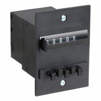
How do pneumatic counters quantify cycles of operation?
Pneumatic counters quantify cycles of operation by using air pressure to increment a mechanical counting mechanism. These devices are typically used in environments where electrical counters might not be suitable, such as in explosive atmospheres or where electrical interference is a concern.
The operation begins with a pneumatic signal, usually in the form of a pulse of compressed air. This pulse is generated by the machine or process being monitored, each time a specific event or cycle occurs. The pneumatic counter is connected to the source of these pulses via a pneumatic line.
Inside the counter, the air pulse actuates a diaphragm or piston. This movement is then mechanically linked to a ratchet and pawl mechanism or a similar mechanical counting device. Each pulse causes the ratchet to advance by one tooth, which in turn rotates a gear or wheel that displays the count. The display is typically a series of numbered wheels or dials that show the total number of cycles or events that have occurred.
Pneumatic counters are designed to be highly reliable and durable, often constructed from materials that can withstand harsh industrial environments. They do not require electrical power, making them ideal for remote or hazardous locations. The accuracy of the count depends on the consistency of the pneumatic pulses and the mechanical integrity of the counter.
These counters can be reset manually or automatically, depending on the design, allowing for repeated use in various applications. They are commonly used in manufacturing processes, packaging lines, and other industrial applications where tracking the number of operations is critical for maintenance, quality control, or production monitoring.
What types of sensor mounting hardware are available for air cylinders?
Various types of sensor mounting hardware are available for air cylinders to ensure accurate and efficient sensor placement. These include:
1. **Magnetic Sensor Brackets**: Designed to hold magnetic sensors in place, these brackets are typically adjustable and can be mounted directly onto the cylinder body. They are often used with reed or Hall effect sensors.
2. **T-Slot Mounts**: These mounts fit into the T-slot grooves commonly found on the cylinder body. They allow for easy installation and adjustment of sensors along the length of the cylinder.
3. **Tie-Rod Mounts**: Used with tie-rod cylinders, these mounts attach sensors to the tie rods, providing a stable and secure position for sensor operation.
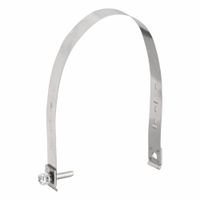
4. **Band Clamps**: These are flexible metal or plastic bands that wrap around the cylinder body, allowing sensors to be mounted at various positions. They are adjustable and can accommodate different cylinder sizes.
5. **Dovetail Mounts**: These mounts slide into dovetail grooves on the cylinder, offering a secure and adjustable method for sensor placement.
6. **Profile Mounts**: Designed for cylinders with a specific profile, these mounts ensure that sensors are aligned correctly with the cylinder's movement.
7. **Bracket Mounts**: These are general-purpose mounts that can be attached to various parts of the cylinder or its environment, providing flexibility in sensor positioning.
8. **Magnetic Piston Mounts**: For cylinders with magnetic pistons, these mounts allow sensors to detect the piston's position through the cylinder wall.
9. **Custom Mounts**: In some cases, custom-designed mounts are used to meet specific application requirements, ensuring optimal sensor performance.
These mounting options provide versatility and adaptability, allowing sensors to be positioned accurately for optimal performance in monitoring cylinder operations.
How do pneumatic actuator sensors communicate with other analytic and process equipment?
Pneumatic actuator sensors communicate with other analytic and process equipment primarily through various signal transmission methods, which include:
1. **4-20 mA Current Loop**: This is a widely used method where the sensor converts physical parameters into a current signal ranging from 4 to 20 mA. This signal is transmitted over a pair of wires to a control system or PLC (Programmable Logic Controller), which interprets the signal to monitor and control the actuator's position or status.
2. **Digital Communication Protocols**: Protocols such as HART (Highway Addressable Remote Transducer), Foundation Fieldbus, and Profibus are used for more complex communication. These protocols allow for bidirectional communication, enabling not only the transmission of sensor data but also the reception of control commands and diagnostic information.
3. **Wireless Communication**: Wireless technologies like WirelessHART and ISA100.11a are increasingly used for remote monitoring and control. These systems use radio frequency signals to transmit data between the sensor and the control system, reducing the need for extensive wiring and allowing for flexible installation.
4. **Modbus**: This is a serial communication protocol that can be used over RS-485 or TCP/IP networks. It allows for the integration of pneumatic actuator sensors with other devices in a network, facilitating data exchange and process control.
5. **Analog Signals**: In some cases, sensors may output simple analog voltage signals (e.g., 0-10V) that are interpreted by connected equipment to determine actuator status.
These communication methods enable seamless integration of pneumatic actuator sensors with process control systems, allowing for real-time monitoring, diagnostics, and control, which enhances process efficiency and reliability.
What are the benefits of using pneumatic actuator sensors in industrial applications?
Pneumatic actuator sensors offer several benefits in industrial applications:
1. **Precision and Control**: These sensors provide accurate feedback on the position and movement of the actuator, enabling precise control of machinery and processes. This precision is crucial for maintaining product quality and consistency.
2. **Reliability and Durability**: Pneumatic systems are known for their robustness and ability to operate in harsh environments. The sensors used in these systems are designed to withstand extreme temperatures, dust, and moisture, ensuring long-term reliability.
3. **Safety**: Pneumatic actuator sensors enhance safety by providing real-time data that can be used to monitor and control the operation of machinery. This helps in preventing accidents and equipment damage by allowing for quick responses to any anomalies.
4. **Energy Efficiency**: By providing accurate feedback, these sensors help optimize the use of compressed air, reducing energy consumption and operational costs. Efficient use of energy also contributes to a smaller carbon footprint.
5. **Ease of Integration**: Pneumatic actuator sensors can be easily integrated into existing systems. They are compatible with various control systems and can be used in conjunction with other types of sensors for comprehensive monitoring and control.
6. **Cost-Effectiveness**: Compared to other types of actuators, pneumatic systems are generally more cost-effective. The sensors used in these systems are also relatively inexpensive, making them an economical choice for many industries.
7. **Versatility**: These sensors can be used in a wide range of applications, from simple on/off control to complex automation systems. They are suitable for industries such as manufacturing, automotive, food and beverage, and pharmaceuticals.
8. **Reduced Maintenance**: The simplicity of pneumatic systems, combined with the durability of the sensors, results in lower maintenance requirements and costs, minimizing downtime and increasing productivity.


