Call +(254) 703 030 000 / 751 483 999 / 721 704 777
.....Read More


Frequently Asked Questions
What are hydraulic valves and how do they work?
Hydraulic valves are mechanical devices used to control the flow, pressure, and direction of hydraulic fluid within a hydraulic system. They are essential components in various applications, from heavy machinery to industrial automation.
How they work:
At their core, hydraulic valves operate by manipulating the path of hydraulic fluid. They consist of a body, an internal mechanism (like a spool, poppet, or ball), and actuators (manual, mechanical, electrical, or pneumatic) that move the internal mechanism. When the mechanism is moved, it either opens or closes specific flow paths, diverting or blocking the fluid's passage. This control allows for precise management of hydraulic actuators like cylinders and motors.
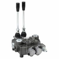
Types of hydraulic valves: * Directional control valves: These valves direct the flow of fluid to control the movement of actuators. They can be 2-way, 3-way, or 4-way, referring to the number of ports and switching positions.
* Pressure control valves: These regulate the pressure within the hydraulic system, preventing damage and ensuring consistent operation. Examples include relief valves, reducing valves, and sequence valves.
* Flow control valves: These adjust the rate of fluid flow, thereby controlling the speed of actuators. They can be fixed or adjustable.By combining different types of valves, complex hydraulic circuits can be designed to achieve precise and powerful control over various mechanical operations.
How do hydraulic flow control valves regulate fluid flow?
Hydraulic flow control valves regulate fluid flow by adjusting the size of an opening through which the fluid passes. This opening is often a variable orifice. By changing the size of this orifice, the valve alters the resistance to flow, thereby controlling the flow rate.
There are several types of flow control valves, including needle valves, globe valves, and gate valves. Needle valves, for instance, use a tapered needle to precisely control the opening, allowing for fine adjustments to the flow rate. Globe valves use a movable disk or plug that seats against a body, restricting flow as it moves closer to the seat. Gate valves use a gate or wedge-shaped disc to open or close the flow path, primarily used for on/off control rather than precise flow regulation.
Some flow control valves are pressure-compensated, meaning they maintain a constant flow rate regardless of changes in system pressure. These valves are critical in applications where a consistent speed or movement is required, even under varying load conditions. Other valves may be temperature-compensated to account for changes in fluid viscosity due to temperature fluctuations. Ultimately, the objective of a flow control valve is to provide precise and reliable control over the speed of actuators or the rate of fluid transfer in a hydraulic system.
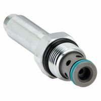
What is the function of a hydraulic cartridge valve?
A hydraulic cartridge valve is a compact, self-contained hydraulic component designed to control the flow, pressure, or direction of hydraulic fluid within a system. Unlike traditional screw-in or manifold-mounted valves, cartridge valves are typically inserted into a cavity in a manifold or block, allowing for a more integrated and space-efficient design.
Their primary functions include: * **Directional Control:** Some cartridge valves act as directional control valves, directing fluid flow to different parts of a circuit to actuate cylinders or motors.
* **Pressure Control:** Pressure relief, reducing, or sequence valves are common cartridge types, regulating the system pressure to protect components or ensure proper operation.
* **Flow Control:** Orifice and flow control valves manage the rate of fluid flow, controlling the speed of actuators.
* **Check Valves:** These allow fluid to flow in one direction only, preventing backflow and maintaining pressure.Cartridge valves are highly versatile and widely used in various hydraulic applications due to their compact size, ease of installation, and robust construction. They contribute to simplifying hydraulic circuits, reducing leakage points, and improving overall system efficiency.
How do hydraulic flow dividers ensure synchronized motion?
Hydraulic flow dividers ensure synchronized motion by splitting a single input flow into multiple output flows, maintaining a consistent ratio between them. This is achieved through various designs, primarily gear-type or spool-type dividers.
Gear-type flow dividers consist of multiple gears on a common shaft, with each gear driving a separate hydraulic motor or cylinder. As fluid enters, it rotates the gears, and since they are mechanically linked, they rotate at the same speed, ensuring that the fluid exiting each section is proportional, thus synchronizing the movement of attached actuators.
Spool-type flow dividers, on the other hand, use precisely machined spools that move within a housing to divide the flow. They can be pressure-compensated, meaning they adjust to variations in load pressure on the different outputs, maintaining the desired flow ratio even under uneven loads. This is crucial for applications where the actuators might encounter differing resistances.
Both types work on the principle of volumetric displacement. By accurately proportioning the fluid volume delivered to each actuator, hydraulic flow dividers ensure that multiple cylinders or motors extend or retract at the same rate, providing synchronized and controlled motion in complex hydraulic systems.
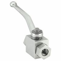
What is the purpose of a hydraulic ball valve?
A hydraulic ball valve is a type of quarter-turn valve that uses a hollow, pivoting ball to control the flow of fluid. Its primary purpose is to stop, start, or divert the flow of hydraulic fluid within a system. When the valve is open, the hole through the ball is aligned with the fluid flow, allowing it to pass. When the valve is closed, the ball is rotated 90 degrees, blocking the flow.
Key purposes and advantages of hydraulic ball valves include: * **On/Off Control:** They provide quick and efficient on/off functionality, making them ideal for isolating sections of a hydraulic circuit or stopping the flow to specific components.
* **Low Pressure Drop:** When fully open, the straight-through design of the ball results in minimal resistance to flow, leading to a low-pressure drop across the valve. This helps maintain system efficiency.
* **Durability and Reliability:** Designed to withstand high pressures and demanding hydraulic environments, they are known for their robust construction and long service life.
* **Tight Sealing:** Ball valves offer excellent sealing capabilities when closed, preventing leakage and ensuring the integrity of the hydraulic system.
* **Compact Design:** Their relatively compact size makes them suitable for applications where space is limited.
* **Versatility:** They are used in a wide range of hydraulic applications across various industries, including construction, agriculture, manufacturing, and mobile equipment.In essence, a hydraulic ball valve serves as a reliable and effective control mechanism for managing the flow of high-pressure hydraulic fluids.
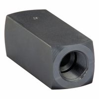
How do hydraulic check valves maintain directional flow?
Hydraulic check valves are essential components in hydraulic systems, designed to ensure unidirectional flow of fluid. They achieve this by utilizing a simple yet effective mechanism. Inside the valve, there's typically a movable component, such as a ball, poppet, or disc, held against a seat by a spring or by the pressure of the fluid in the desired flow direction.
When fluid flows in the intended direction (the "forward" direction), the pressure of the fluid overcomes the spring force or the opposing pressure, pushing the movable component off its seat. This opens a path for the fluid to pass through the valve with minimal resistance.
However, if the fluid attempts to flow in the opposite (reverse) direction, the pressure of the fluid acts on the movable component, pushing it firmly against its seat. This action effectively seals the flow path, preventing any backflow of fluid. The spring force also assists in holding the component in the closed position, ensuring a tight seal.
This one-way flow capability is critical in many hydraulic applications. For instance, check valves prevent the draining of accumulators, maintain pressure in certain parts of a circuit, protect pumps from reverse flow, and ensure the proper sequencing of operations in complex systems. Their reliability and simplicity make them indispensable for maintaining the integrity and efficiency of hydraulic circuits.
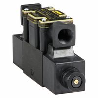
What are hydraulic stack valves and their benefits?
Hydraulic stack valves are a type of modular hydraulic valve system designed for efficient and compact control of hydraulic circuits. Unlike traditional individual valves, stack valves are built in layers or "stacks," with each layer performing a specific hydraulic function (e.g., directional control, pressure relief, flow control). These layers are bolted together, sharing common manifold passages for pressure, tank, and work ports, which significantly reduces external piping and potential leakage points.
The primary benefits of hydraulic stack valves include: * Compact Design: Their layered construction allows for a much smaller footprint compared to systems with discrete valves, making them ideal for applications with limited space.
* Reduced Leakage: By minimizing external tubing and connections, the risk of leaks is significantly decreased, leading to a cleaner and safer operating environment, and less fluid loss.
* Simplified Assembly and Maintenance: The modular nature allows for easier assembly and replacement of individual valve functions without disturbing the entire system. Troubleshooting can also be more straightforward.
* Improved Efficiency: Shorter internal passages and reduced pressure drops can lead to better system efficiency.
* Customization and Flexibility: Various valve functions can be easily combined and reconfigured to meet specific application requirements, offering high flexibility in system design.These benefits make hydraulic stack valves a popular choice in a wide range of mobile and industrial hydraulic machinery, including construction equipment, agricultural machinery, and manufacturing systems.
How do hydraulic manifold valves operate in a system?
Hydraulic manifold valves are essential components in hydraulic systems, acting as a central hub for fluid control. They integrate multiple hydraulic valves (such as directional, pressure, and flow control valves) into a single block, eliminating the need for extensive piping and fittings. This integration simplifies system design, reduces leak points, and makes maintenance easier.
In operation, fluid from the hydraulic pump enters the manifold block. Internal passages within the manifold are precisely machined to route the fluid to and from various components like actuators (cylinders or motors). Each valve mounted on the manifold controls a specific aspect of the fluid's behavior. For instance, a directional control valve dictates the path of the fluid, determining if it goes to extend or retract a cylinder. A pressure relief valve prevents over-pressurization by diverting excess fluid back to the reservoir, while a flow control valve regulates the speed of an actuator by limiting the fluid flow.
When a signal (electrical, manual, or pilot) activates a valve on the manifold, it changes its internal configuration, allowing fluid to flow in a specific direction or at a controlled pressure/flow rate. This directed fluid then powers the connected actuators to perform the desired mechanical work. The compact design of manifolds allows for a more efficient and responsive hydraulic system, crucial in applications ranging from industrial machinery to mobile equipment.
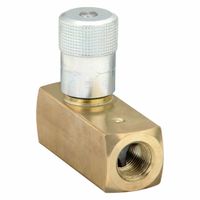
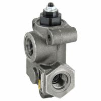
What is the role of hydraulic selector valves in a circuit?
Hydraulic selector valves are crucial components in a hydraulic circuit, primarily responsible for directing the flow of hydraulic fluid to different parts of the system. Their main role is to control which actuator or function receives pressurized fluid at any given time. This is achieved by physically switching or diverting the fluid path within the valve.
For instance, in a system with multiple hydraulic cylinders, a selector valve can be used to extend one cylinder while retracting another, or to operate a different function altogether. They allow for sequential or selective operation of various hydraulic components, optimizing the system's efficiency and functionality. Depending on their design, selector valves can be manually operated, solenoid-actuated, or pilot-operated, offering flexibility in control methods. Their ability to manage fluid distribution makes them fundamental for complex hydraulic machinery requiring precise and diverse operations.
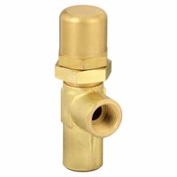
How do hydraulic pressure relief valves protect system components?
Hydraulic pressure relief valves are crucial safety devices designed to protect hydraulic systems from damage caused by excessive pressure. They achieve this by diverting excess fluid flow back to the reservoir when the system pressure exceeds a predetermined set point. This prevents pressure buildup that could otherwise lead to component failure, leaks, or even catastrophic rupture of hoses and pipes.
When the pressure in the system reaches the valve's set pressure, the valve opens, creating an alternative path for the fluid. This bypass ensures that the system pressure does not continue to climb, safeguarding components like pumps, cylinders, and motors from overpressure. Once the pressure drops back to an acceptable level, the valve closes, allowing the fluid to continue its intended path within the system.
These valves are essential for maintaining the integrity and longevity of hydraulic machinery, ensuring safe and efficient operation. They are commonly found in a wide range of applications, from heavy industrial machinery to agricultural equipment and mobile hydraulics.