.....Read More

Frequently Asked Questions

What are the main components of an air conditioning and refrigeration control system?

The main components of an air conditioning and refrigeration control system include: 1. **Thermostat**: This device senses the temperature of the environment and maintains it at a set point by controlling the operation of the system. 2. **Compressor**: It compresses the refrigerant, increasing its pressure and temperature, and circulates it through the system. 3. **Condenser**: This component dissipates heat from the refrigerant to the outside air, condensing it from a gas to a liquid. 4. **Expansion Valve**: It reduces the pressure of the refrigerant, allowing it to expand and cool before entering the evaporator. 5. **Evaporator**: The refrigerant absorbs heat from the indoor air, cooling it, and then evaporates back into a gas. 6. **Refrigerant**: A fluid that circulates through the system, absorbing and releasing heat to provide cooling. 7. **Sensors**: These include temperature, pressure, and humidity sensors that provide data to the control system for efficient operation. 8. **Control Board**: The central unit that processes input from sensors and the thermostat to regulate the system's components. 9. **Fans and Blowers**: These circulate air over the evaporator and condenser coils to facilitate heat exchange. 10. **Dampers**: Used in duct systems to control airflow and direct it to different zones or areas. 11. **Relays and Contactors**: Electrical switches that control the power to the compressor and fans based on signals from the control board. 12. **Safety Devices**: These include pressure switches, overload protectors, and fuses to prevent damage to the system. 13. **Defrost Control**: In refrigeration systems, this component manages the defrost cycle to prevent ice buildup on the evaporator. These components work together to regulate temperature, humidity, and air quality, ensuring efficient and reliable operation of air conditioning and refrigeration systems.

How do pressure controls work in air conditioning and refrigeration systems?

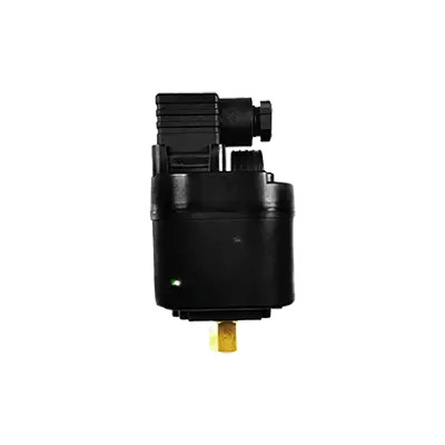
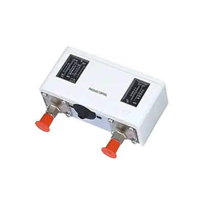
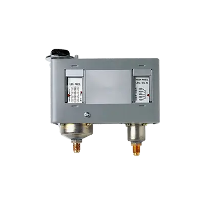
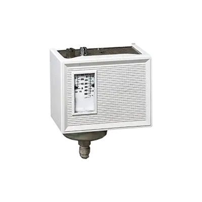
Pressure controls in air conditioning and refrigeration systems regulate the operation of compressors and maintain system efficiency and safety. They are primarily used to monitor and control the pressure of refrigerants within the system. 1. **High-Pressure Controls**: These are safety devices that prevent the system from operating at excessively high pressures, which can cause damage or failure. When the pressure exceeds a set limit, the high-pressure control will shut down the compressor to prevent damage. 2. **Low-Pressure Controls**: These controls ensure that the system does not operate at pressures that are too low, which can lead to inefficient operation or freezing of the evaporator coil. If the pressure drops below a predetermined level, the low-pressure control will stop the compressor. 3. **Dual Pressure Controls**: These combine both high and low-pressure controls in a single device, providing comprehensive protection and control. They are often used in systems where space is limited or where both high and low-pressure conditions need to be monitored closely. 4. **Differential Pressure Controls**: These are used to maintain a specific pressure difference between two points in the system, such as across a filter or an evaporator coil. They help ensure optimal flow and heat exchange efficiency. 5. **Adjustable Pressure Controls**: These allow for manual setting of pressure limits, providing flexibility to adapt to different operating conditions or refrigerants. Pressure controls are typically connected to the system via pressure ports and are calibrated to specific pressure settings. They can be mechanical, using diaphragms or bellows, or electronic, using sensors and microprocessors for more precise control. Properly functioning pressure controls are essential for the safe, efficient, and reliable operation of air conditioning and refrigeration systems.

What is the function of refrigeration cold controls?

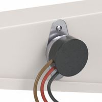
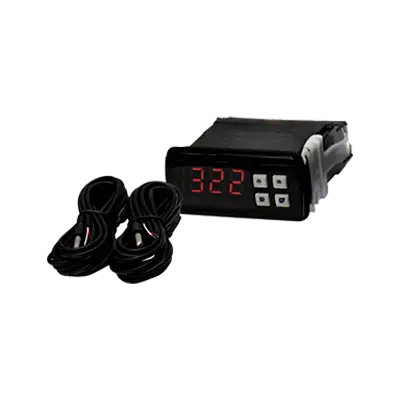
Refrigeration cold controls, also known as thermostats, are critical components in refrigeration systems. Their primary function is to regulate and maintain the desired temperature within the refrigeration unit. They achieve this by sensing the temperature inside the refrigerator or freezer and controlling the operation of the compressor accordingly. When the temperature inside the unit rises above the set point, the cold control activates the compressor, which circulates refrigerant through the system to remove heat and lower the temperature. Once the desired temperature is reached, the cold control deactivates the compressor, conserving energy and preventing overcooling. Cold controls ensure the preservation of food and other perishable items by maintaining a consistent and optimal temperature, preventing spoilage and bacterial growth. They also contribute to energy efficiency by minimizing the compressor's run time, reducing electricity consumption and operational costs. Additionally, cold controls can include features like adjustable temperature settings, allowing users to customize the cooling level based on specific needs. Some advanced models may incorporate digital displays and electronic sensors for more precise temperature management. Overall, refrigeration cold controls are essential for the effective and efficient operation of refrigeration systems, ensuring both food safety and energy conservation.

How do defrost thermostats prevent frost buildup?

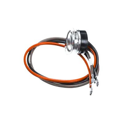
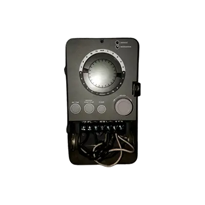
Defrost thermostats prevent frost buildup by regulating the defrost cycle in refrigeration systems. They are integral components in appliances like refrigerators and freezers, where they ensure efficient operation by preventing excessive frost accumulation on the evaporator coils. Here's how they work: 1. **Temperature Monitoring**: The defrost thermostat is attached to the evaporator coil and continuously monitors its temperature. It is designed to activate the defrost cycle when the coil temperature drops to a predetermined level, indicating frost buildup. 2. **Activation of Defrost Cycle**: Once the thermostat detects the low temperature, it closes an electrical circuit to activate the defrost heater. The heater is usually located near or on the evaporator coils and generates heat to melt the accumulated frost. 3. **Controlled Defrosting**: The defrost thermostat ensures that the defrost cycle is only active for as long as necessary. It prevents overheating by opening the circuit once the coil reaches a specific higher temperature, indicating that the frost has melted. This precise control helps maintain energy efficiency and prevents damage to the appliance. 4. **Cycle Termination**: After the defrost cycle, the thermostat resets, allowing the refrigeration system to return to its normal cooling operation. This cycle repeats as needed, based on the thermostat's temperature readings. By managing the defrost cycle, defrost thermostats maintain optimal cooling efficiency, prevent excessive energy consumption, and extend the lifespan of the appliance. They ensure that frost does not impede airflow over the coils, which could otherwise lead to reduced cooling performance and increased energy usage.

How do room air conditioner temperature controls operate PTACs?

Room air conditioner temperature controls in Packaged Terminal Air Conditioners (PTACs) operate through a combination of sensors, thermostats, and control algorithms to maintain the desired room temperature. The process begins with the user setting a preferred temperature on the PTAC's control panel or remote control. This setpoint is communicated to the unit's thermostat, which continuously monitors the ambient room temperature using built-in sensors. When the room temperature deviates from the setpoint, the PTAC's control system activates the necessary components to adjust the temperature. If the room is warmer than desired, the cooling cycle is initiated. The compressor starts, circulating refrigerant through the evaporator coils to absorb heat from the room air. The fan then blows the cooled air back into the room, lowering the temperature. Conversely, if the room is cooler than the setpoint, and the PTAC has a heating function, the heating cycle is activated. This can involve either electric resistance heating or a heat pump mechanism, depending on the PTAC model. The fan circulates warm air into the room until the desired temperature is reached. The control system uses feedback from the temperature sensors to modulate the compressor and fan speeds, optimizing energy efficiency and maintaining a stable room temperature. Some advanced PTACs incorporate additional features like programmable timers, occupancy sensors, and energy-saving modes to further enhance control and efficiency. Overall, the temperature controls in PTACs are designed to provide precise and efficient climate control, ensuring comfort while minimizing energy consumption.

What is the role of potential relays in safeguarding motors and start capacitors?

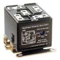
Potential relays play a crucial role in safeguarding motors and start capacitors by controlling the start winding circuit in single-phase motors. They are primarily used in applications involving hermetic compressors, such as those found in refrigeration and air conditioning systems. The potential relay ensures that the start capacitor is disconnected from the circuit once the motor reaches a certain speed, preventing damage to both the motor and the capacitor. When a motor starts, the start capacitor provides the necessary phase shift and additional torque to initiate rotation. The potential relay monitors the voltage across the start winding. As the motor accelerates, the back EMF (electromotive force) generated by the motor increases. Once this voltage reaches a predetermined level, the potential relay activates, opening its normally closed contacts and disconnecting the start capacitor from the circuit. This disconnection is vital for several reasons: 1. **Prevents Overheating**: Continuous connection of the start capacitor can lead to overheating, potentially causing the capacitor to fail or even explode. 2. **Protects Motor Windings**: By ensuring the start winding is only engaged during startup, the potential relay prevents excessive current from flowing through the motor windings, reducing the risk of overheating and damage. 3. **Enhances Efficiency**: Disconnecting the start capacitor once the motor reaches operational speed improves overall efficiency and reduces energy consumption. 4. **Extends Component Life**: By preventing unnecessary stress on the start capacitor and motor windings, the potential relay extends the lifespan of these components, reducing maintenance costs and downtime. In summary, potential relays are essential for the safe and efficient operation of motors with start capacitors, ensuring that these components are only engaged when necessary and disconnected promptly to prevent damage.

How do compressor hard start kits assist in starting high-powered components?

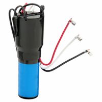
Compressor hard start kits assist in starting high-powered components by providing an initial boost of electrical power to overcome the inertia and resistance that compressors face during startup. These kits typically consist of a start capacitor and a potential relay or a PTC (Positive Temperature Coefficient) thermistor. The start capacitor temporarily stores electrical energy and releases it quickly to the compressor motor, providing the extra torque needed to start the motor efficiently. This is particularly useful for high-powered components that require a significant amount of energy to initiate movement, such as air conditioning compressors or refrigeration units. The potential relay or PTC thermistor plays a crucial role in disconnecting the start capacitor from the circuit once the motor reaches a certain speed. The potential relay senses the voltage increase as the motor accelerates and opens the circuit to the start capacitor, preventing it from remaining in the circuit and potentially causing damage. In systems using a PTC thermistor, the thermistor increases in resistance as it heats up, effectively removing the start capacitor from the circuit. By providing this initial power boost, hard start kits reduce the strain on the electrical system and the compressor motor, leading to improved efficiency and longevity. They help prevent issues such as voltage drops, overheating, and motor stalling, which can occur when high-powered components struggle to start. This assistance is particularly beneficial in environments with low voltage supply or where the compressor frequently cycles on and off. Overall, hard start kits enhance the reliability and performance of high-powered components by ensuring a smoother and more efficient startup process.