Call +(254) 703 030 000 / 751 483 999 / 721 704 777
- Home
- Electrical
- Industrial Controls Automation And Machine Safety
- Operator Switches Pilot Lights
- Selector Rotary Switches
.....Read More
Frequently Asked Questions
What is a selector switch and how does it work?
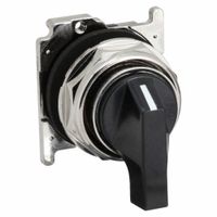
A selector switch is an electromechanical device used to control the operation of electrical circuits by selecting one or more options from multiple available settings. It is commonly used in industrial and commercial applications to manage machinery, lighting, and other electrical equipment.
The switch typically consists of a rotary or lever mechanism that can be turned or moved to different positions, each corresponding to a specific circuit configuration or operational mode. The positions are often labeled to indicate their function, such as "On," "Off," "Auto," "Manual," or specific speed settings.
Selector switches work by altering the path of electrical current through internal contacts. When the switch is moved to a particular position, it connects specific contacts, allowing current to flow through the desired circuit. This action can either energize or de-energize components, such as motors, lights, or relays, depending on the configuration.
There are several types of selector switches, including:
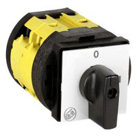
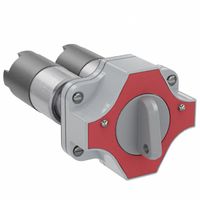
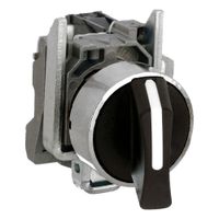
1. **Rotary Selector Switches**: These have a rotating knob or dial that can be turned to select different positions. They are often used for multi-position control.
2. **Lever Selector Switches**: These use a lever that can be moved to different positions, providing a more tactile control option.
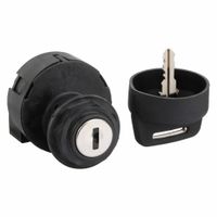
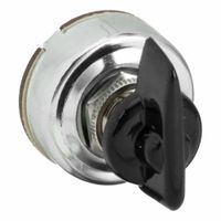
3. **Key-operated Selector Switches**: These require a key to change positions, offering an added layer of security.
Selector switches can be momentary or maintained. Momentary switches return to a default position when released, while maintained switches stay in the selected position until manually changed.
Overall, selector switches provide a simple and effective means of controlling complex electrical systems by allowing users to easily select and change operational modes.
What are the different types of rotary switches?
Rotary switches are versatile components used to control multiple circuits with a single switch. The different types include:
1. **Single-Pole, Single-Throw (SPST):** This basic type controls one circuit and is either on or off.
2. **Single-Pole, Double-Throw (SPDT):** This switch connects a single input to one of two outputs, allowing for two positions.
3. **Double-Pole, Single-Throw (DPST):** It controls two separate circuits simultaneously with a single action, having one on and one off position.
4. **Double-Pole, Double-Throw (DPDT):** This type can control two circuits and switch between two outputs for each, offering four positions.
5. **Three-Pole, Double-Throw (3PDT):** Similar to DPDT but controls three circuits, often used in more complex applications.
6. **Four-Pole, Double-Throw (4PDT):** Controls four circuits, providing more versatility for complex switching needs.
7. **Shorting (Make-Before-Break):** Ensures the new connection is made before the old one is broken, preventing circuit interruption.
8. **Non-Shorting (Break-Before-Make):** Breaks the current connection before making a new one, used where circuit isolation is necessary.
9. **Binary Coded Decimal (BCD):** Used in digital applications, it converts rotary positions into binary code.
10. **Multi-Deck:** Consists of multiple layers (decks) to control several circuits, each deck acting as a separate switch.
11. **Thumbwheel:** A compact rotary switch operated by a thumbwheel, often used in settings where space is limited.
12. **Rotary DIP:** Combines rotary and dual in-line package (DIP) switch features, used in electronic devices for setting configurations.
13. **Wafer Switch:** Composed of multiple wafers stacked together, allowing for complex switching arrangements.
These types cater to various applications, from simple on/off functions to complex multi-circuit control, in industries like electronics, telecommunications, and industrial machinery.
How do you install a selector switch in a control panel?
1. **Safety First**: Turn off all power to the control panel. Use lockout/tagout procedures to ensure safety.
2. **Select Location**: Choose an appropriate location on the control panel door or enclosure for the selector switch, ensuring it is easily accessible and visible.
3. **Mark and Drill**: Mark the center point for the switch hole using a template or the switch body as a guide. Drill a pilot hole, then use a hole saw or step drill bit to create the correct-sized hole for the switch.
4. **Prepare the Switch**: Disassemble the selector switch if necessary, separating the front operator from the contact block.
5. **Install the Operator**: Insert the front operator of the selector switch through the hole from the outside of the panel. Secure it with the provided locking nut or mounting hardware.
6. **Attach the Contact Block**: From inside the panel, attach the contact block to the operator. Ensure it is securely fastened and aligned properly.
7. **Wiring**: Connect the wires to the contact block terminals according to the wiring diagram. Use appropriate wire sizes and terminal connectors. Ensure connections are tight and secure.
8. **Labeling**: Label the switch position and function on the panel for clarity and ease of use.
9. **Testing**: Restore power to the control panel. Test the selector switch to ensure it operates correctly and controls the intended circuit or device.
10. **Final Inspection**: Check all connections and ensure the switch is securely mounted. Verify that the panel door closes properly without interference.
11. **Documentation**: Update any schematics or documentation to reflect the addition of the selector switch.
What are the applications of rotary selector switches in industrial systems?
Rotary selector switches are versatile components used in industrial systems for various applications due to their ability to control multiple circuits with a single switch. Here are some key applications:
1. **Control Panels**: Rotary selector switches are commonly used in control panels to select different operational modes, such as manual, automatic, or off. They provide a clear and reliable method for operators to change settings.
2. **Motor Control**: In motor control applications, these switches are used to select different speeds or directions for motors. They can switch between forward, reverse, and stop functions, making them essential in conveyor systems and machinery.
3. **Testing and Calibration**: Rotary switches are used in testing and calibration equipment to select different test modes or calibrate instruments. They allow precise control over the testing parameters.
4. **Power Distribution**: In power distribution systems, rotary selector switches are used to route power to different circuits or loads. They can be used to switch between main and backup power sources, ensuring continuity of operations.
5. **Signal Switching**: These switches are used in signal processing applications to select different input or output signals. This is crucial in communication systems and audio-visual equipment.
6. **Process Control**: In process control systems, rotary selector switches are used to select different process variables or control loops. They enable operators to switch between different process parameters easily.
7. **Safety Systems**: Rotary switches are used in safety systems to enable or disable safety functions. They provide a reliable means to control emergency stop functions or safety interlocks.
8. **Lighting Control**: In industrial lighting systems, rotary selector switches are used to control different lighting zones or intensity levels, providing flexibility in lighting management.
Overall, rotary selector switches are integral to industrial systems, offering reliability, ease of use, and flexibility in controlling various functions and processes.
How do you choose the right selector switch for hazardous locations?
To choose the right selector switch for hazardous locations, consider the following factors:
1. **Classification**: Identify the hazardous area classification (Class, Division, and Group) to ensure the switch is suitable for the specific environment, such as Class I (flammable gases), Class II (combustible dust), or Class III (fibers and flyings).
2. **Certification**: Ensure the switch is certified by relevant authorities (e.g., UL, ATEX, IECEx) for use in hazardous locations. This guarantees compliance with safety standards.
3. **Enclosure Rating**: Select a switch with an appropriate enclosure rating (e.g., NEMA or IP) to protect against environmental factors like dust, water, and corrosion.
4. **Material**: Choose materials that resist corrosion and are compatible with the chemicals present in the environment. Common materials include stainless steel and aluminum.
5. **Temperature Rating**: Ensure the switch can operate within the temperature range of the hazardous location to prevent ignition risks.
6. **Explosion-Proof Design**: Opt for explosion-proof or intrinsically safe designs that prevent ignition of surrounding hazardous substances.
7. **Durability and Reliability**: Consider the switch's mechanical and electrical endurance to ensure long-term reliability in harsh conditions.
8. **Ease of Operation**: Ensure the switch is user-friendly and can be operated with protective gear if necessary.
9. **Maintenance and Accessibility**: Choose a switch that allows for easy maintenance and inspection without compromising safety.
10. **Cost and Availability**: Balance cost with the availability of replacement parts and support services.
By considering these factors, you can select a selector switch that ensures safety, compliance, and functionality in hazardous locations.
What is the difference between a selector switch and a potentiometer?
A selector switch and a potentiometer are both used to control electrical circuits, but they serve different functions and operate differently.
A selector switch is a mechanical device used to open or close electrical circuits by rotating or sliding a switch to different positions. It is typically used to select between multiple circuit paths or modes of operation. Selector switches are commonly found in control panels and are used for applications like selecting motor speeds, changing operational modes, or switching between different power sources. They are characterized by discrete positions, such as "on/off" or "low/medium/high," and do not provide variable control.
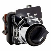
A potentiometer, on the other hand, is an electrical component that functions as a variable resistor. It is used to adjust voltage levels within a circuit by varying the resistance. Potentiometers have a continuous range of adjustment, allowing for fine-tuning of parameters like volume, brightness, or speed. They consist of a resistive element and a movable wiper that slides along the element, changing the resistance and, consequently, the output voltage. Potentiometers are commonly used in audio equipment, light dimmers, and other applications requiring smooth, variable control.
In summary, the key differences are:
- Function: Selector switches choose between discrete options, while potentiometers provide continuous variable control.
- Operation: Selector switches have fixed positions, whereas potentiometers allow for smooth adjustment.
- Application: Selector switches are used for mode or path selection, while potentiometers are used for adjusting levels or intensities.
How do you replace or repair a damaged selector switch?
1. **Safety First**: Turn off the power supply to the device or circuit where the selector switch is located. Use a multimeter to ensure there is no electrical current.
2. **Access the Switch**: Remove any panels or covers to access the selector switch. This may require unscrewing or unclipping parts of the device.
3. **Identify the Switch**: Note the type and specifications of the selector switch. Take pictures or label wires to ensure correct reconnection.
4. **Remove the Damaged Switch**: Disconnect the wires from the switch terminals. Unscrew or unclip the switch from its mounting.
5. **Select a Replacement**: Obtain a replacement switch that matches the specifications of the original, including voltage, current rating, and number of positions.
6. **Install the New Switch**: Mount the new switch in place of the old one. Reconnect the wires to the correct terminals, referring to your notes or photos.
7. **Test the Installation**: Before reassembling the device, turn the power back on and test the switch to ensure it functions correctly.
8. **Reassemble the Device**: Once confirmed, turn off the power again, reassemble any panels or covers, and secure them in place.
9. **Final Test**: Turn the power back on and perform a final test to ensure everything is working as expected.
10. **Safety Check**: Ensure all tools and materials are cleared from the work area and that the device is safe for regular use.
