Call +(254) 703 030 000 / 751 483 999 / 721 704 777
- Home
- Electrical
- Fuses Circuit Breakers Safety Switches
- Circuit Breakers Panelboards Load Centers
.....Read More
Frequently Asked Questions
What is the difference between a circuit breaker and a fuse?
A circuit breaker and a fuse are both protective devices used in electrical circuits to prevent damage from overcurrent, but they operate differently and have distinct characteristics.
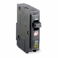
A circuit breaker is an electromechanical switch that automatically interrupts the flow of electricity in a circuit when it detects an overload or short circuit. It can be reset manually or automatically to resume normal operation, making it reusable. Circuit breakers are typically used in residential, commercial, and industrial settings due to their reliability and ease of use. They come in various types, such as thermal, magnetic, and hybrid, each suited for different applications. Circuit breakers can also offer additional features like remote operation and status monitoring.
A fuse, on the other hand, is a simpler device consisting of a metal wire or strip that melts when excessive current flows through it, thereby breaking the circuit. Fuses are single-use devices, meaning they need to be replaced once they have blown. They are generally less expensive than circuit breakers and are often used in smaller or less critical applications. Fuses provide a fast response to overcurrent conditions, which can be advantageous in protecting sensitive equipment.
In summary, the main differences between a circuit breaker and a fuse are their reusability, cost, and application. Circuit breakers are reusable and more versatile, while fuses are single-use and typically less expensive. The choice between the two depends on factors like the specific application, budget, and the level of protection required.
How do I choose the right circuit breaker for my panel?
To choose the right circuit breaker for your panel, follow these steps:
1. **Determine the Load Requirements**: Calculate the total load (in amperes) that the circuit will carry. Sum up the wattage of all devices on the circuit and divide by the voltage (typically 120V or 240V) to find the amperage.
2. **Identify the Circuit Type**: Determine if the circuit is for lighting, outlets, or specific appliances. Different applications may require different types of breakers, such as standard, GFCI (Ground Fault Circuit Interrupter), or AFCI (Arc Fault Circuit Interrupter).
3. **Check Panel Compatibility**: Ensure the breaker is compatible with your panel brand and model. Panels and breakers are often brand-specific, so using the same manufacturer is recommended.
4. **Select the Correct Amperage**: Choose a breaker with an amperage rating that matches or slightly exceeds the calculated load. Common ratings are 15A, 20A, 30A, etc. Ensure it does not exceed the wire's capacity.
5. **Consider Voltage Requirements**: Ensure the breaker matches the circuit's voltage requirements, typically 120V for single-pole and 240V for double-pole breakers.
6. **Evaluate Breaker Type**: Choose between single-pole (for 120V circuits) and double-pole (for 240V circuits) breakers based on your needs.
7. **Safety and Code Compliance**: Ensure the breaker meets local electrical codes and standards. Consult the National Electrical Code (NEC) or a local electrician if unsure.
8. **Future Expansion**: Consider future needs and potential expansion. It might be wise to choose a panel with extra capacity.
9. **Professional Consultation**: If uncertain, consult a licensed electrician to ensure safety and compliance with all regulations.
What is the purpose of a ground fault circuit interrupter (GFCI)?
A Ground Fault Circuit Interrupter (GFCI) is a safety device designed to protect people from electrical shock by monitoring the flow of electricity in a circuit. Its primary purpose is to detect ground faults, which occur when electrical current unintentionally flows outside its intended path, such as through water or a person. This can happen due to damaged wiring, faulty appliances, or contact with water.
The GFCI works by comparing the amount of current flowing into the circuit with the amount returning. Under normal conditions, these should be equal. If the GFCI detects an imbalance as small as 4 to 6 milliamperes, indicating a ground fault, it quickly cuts off the electrical supply, usually within 1/40th of a second. This rapid response minimizes the risk of severe electric shock or electrocution.
GFCIs are commonly installed in areas where electrical circuits may come into contact with water, such as bathrooms, kitchens, laundry rooms, garages, and outdoor spaces. They can be integrated into outlets, circuit breakers, or portable devices, providing flexibility in installation and use.
In addition to protecting against electric shock, GFCIs can also help prevent electrical fires caused by ground faults. By interrupting the circuit when a fault is detected, they reduce the risk of overheating and potential ignition of surrounding materials.
Overall, the purpose of a GFCI is to enhance electrical safety by providing a critical layer of protection against ground faults, thereby safeguarding both people and property from the dangers of electricity.
How do I install a new circuit breaker in a panelboard?
1. **Safety First**: Turn off the main power supply to the panelboard. Use a voltage tester to ensure there is no power.
2. **Remove Panel Cover**: Unscrew and carefully remove the panel cover to access the circuit breakers.
3. **Identify Space**: Locate an available slot for the new circuit breaker. Ensure it matches the amperage and type required for your panel.
4. **Prepare Wires**: Strip about 1/2 inch of insulation from the end of the wire that will connect to the new breaker.
5. **Insert Circuit Breaker**: Align the new breaker with the bus bar and snap it into place. Ensure it is securely attached.
6. **Connect Wires**: Attach the hot wire to the breaker's terminal screw and tighten. Connect the neutral wire to the neutral bus bar and the ground wire to the ground bus bar, if applicable.
7. **Check Connections**: Ensure all connections are tight and secure. Double-check that the breaker is properly seated.
8. **Replace Panel Cover**: Carefully reattach the panel cover and secure it with screws.
9. **Restore Power**: Turn the main power supply back on. Switch the new breaker to the "ON" position.
10. **Test Circuit**: Use a voltage tester or plug in a device to ensure the circuit is functioning correctly.
11. **Label Breaker**: Clearly label the new breaker in the panel for future reference.
12. **Final Safety Check**: Ensure everything is working properly and there are no unusual sounds or smells.
Always follow local electrical codes and consider hiring a licensed electrician if unsure.
What are the signs of a failing circuit breaker?
Signs of a failing circuit breaker include:
1. **Frequent Tripping**: If a circuit breaker trips often, it may indicate an overload, short circuit, or the breaker itself is failing.
2. **Burning Smell**: A burning odor near the electrical panel can suggest overheating or burning of the breaker components.
3. **Physical Damage**: Visible signs of damage such as scorch marks, frayed wires, or melted components can indicate a failing breaker.
4. **Breaker Won't Stay Reset**: If a breaker trips and won't reset, it may be faulty or there could be a persistent fault in the circuit.
5. **Age and Wear**: Older breakers are more prone to failure due to wear and tear over time.
6. **Hot to Touch**: A breaker that is hot to the touch may be overloaded or failing.
7. **Buzzing or Humming Noise**: Unusual noises from the breaker box can indicate electrical arcing or a failing breaker.
8. **Inconsistent Performance**: Flickering lights or intermittent power loss can be signs of a failing breaker.
9. **Corrosion or Rust**: Moisture exposure can lead to corrosion, affecting the breaker's performance.
10. **Loose Connections**: Loose or poor connections can cause overheating and failure.
11. **Breaker Won't Trip**: A breaker that fails to trip during an overload or short circuit is a serious safety hazard.
12. **Discoloration**: Discoloration around the breaker or panel can indicate overheating or burning.
If any of these signs are present, it is crucial to consult a licensed electrician to assess and address the issue to prevent potential electrical hazards.
How do surge protective devices (SPDs) work?
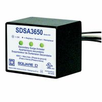
Surge Protective Devices (SPDs) are designed to protect electrical equipment from voltage spikes by limiting the voltage supplied to an electric device by either blocking or shorting to ground any unwanted voltages above a safe threshold. They work by diverting excess voltage away from the protected equipment and into the grounding system, thereby preventing damage.
SPDs typically consist of components like Metal Oxide Varistors (MOVs), Gas Discharge Tubes (GDTs), and Transient Voltage Suppression (TVS) diodes. MOVs are the most common component and function by changing their resistance with the voltage level. Under normal conditions, MOVs have high resistance, but when a surge occurs, their resistance drops, allowing the excess current to be diverted away from the protected equipment.
GDTs operate by ionizing a gas within a sealed tube to create a conductive path for the surge current, effectively shorting the surge to ground. TVS diodes clamp the voltage to a safe level by conducting excess current once the voltage exceeds a certain threshold.
SPDs are categorized into different types based on their application and installation point: Type 1 SPDs are installed at the service entrance to protect against external surges, such as lightning; Type 2 SPDs are installed at distribution panels to protect against internal surges; and Type 3 SPDs are used at the point of use, such as power strips, to protect sensitive electronics.
By providing a low-impedance path to ground for surge currents, SPDs help maintain the integrity of electrical systems, reduce downtime, and extend the lifespan of electronic devices. Regular maintenance and proper installation are crucial for ensuring their effectiveness.
What is the difference between a panelboard and a load center?
A panelboard and a load center are both components used in electrical distribution systems, but they serve slightly different purposes and are used in different contexts.
A panelboard is a component of an electrical distribution system that divides an electrical power feed into subsidiary circuits. It is typically used in commercial and industrial settings. Panelboards are designed to handle higher electrical loads and are often customizable to accommodate specific circuit requirements. They can include features like metering, surge protection, and can be configured for different types of circuit breakers. Panelboards are usually installed in a dedicated electrical room or area and are built to meet specific standards for safety and performance.
A load center, on the other hand, is more commonly used in residential applications. It is a type of panelboard that is designed to distribute electricity to various circuits within a home. Load centers are generally smaller and less complex than commercial panelboards. They are typically installed in accessible locations within a home, such as a garage or basement. Load centers are designed to be user-friendly, allowing homeowners to easily reset circuit breakers. They are often pre-configured with a set number of circuit slots and are designed to handle the electrical load typical of a residential setting.
In summary, the main differences between a panelboard and a load center lie in their application, complexity, and capacity. Panelboards are used in commercial and industrial settings with higher capacity and customization needs, while load centers are used in residential settings with simpler, pre-configured designs.


