Call +(254) 703 030 000 / 751 483 999 / 721 704 777
- Home
- Electrical
- Electrical Connectors Wiring Devices
- Voice Data Connectors Jacks Housings
.....Read More
Frequently Asked Questions
What are the different types of communication connectors and their uses?
Communication connectors are essential components in networking and electronic systems, facilitating the transfer of data, signals, and power. Here are some common types:
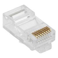
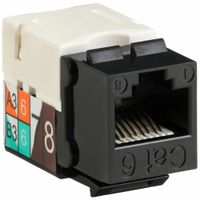
1. **RJ45 (Ethernet Connector):** Used in networking for connecting computers to local area networks (LANs). It supports Ethernet cables like Cat5, Cat5e, Cat6, and Cat6a.
2. **USB (Universal Serial Bus):** Widely used for connecting peripherals to computers, such as keyboards, mice, printers, and external storage devices. Variants include USB-A, USB-B, USB-C, and micro-USB.
3. **HDMI (High-Definition Multimedia Interface):** Transmits high-definition video and audio from devices like computers, gaming consoles, and Blu-ray players to displays like TVs and monitors.
4. **VGA (Video Graphics Array):** An older standard for transmitting video signals from computers to monitors. It is being replaced by digital interfaces like HDMI and DisplayPort.
5. **DisplayPort:** Used for transmitting video and audio from a source to a display. It supports higher resolutions and refresh rates compared to HDMI.
6. **DVI (Digital Visual Interface):** Transmits digital video signals from a computer to a monitor. It comes in DVI-D (digital only), DVI-A (analog only), and DVI-I (integrated digital and analog).
7. **SATA (Serial Advanced Technology Attachment):** Connects storage devices like hard drives and SSDs to the motherboard in computers.
8. **Thunderbolt:** Combines PCI Express and DisplayPort into a single connection, supporting high-speed data transfer and video output.
9. **Fiber Optic Connectors:** Used in high-speed data transmission over long distances. Common types include SC, LC, ST, and MTP/MPO.
10. **Coaxial Connectors:** Used in cable television, internet, and radio frequency applications. Common types include F-type and BNC connectors.
11. **Audio Connectors:** Include 3.5mm jacks, RCA connectors, and XLR connectors, used for transmitting audio signals in consumer electronics and professional audio equipment.
How do you properly install Ethernet switches and connect devices?
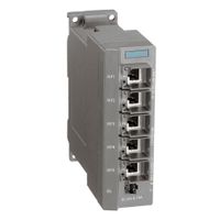
1. **Select the Right Switch**: Choose a switch that meets your network needs, considering the number of ports, speed (Gigabit or Fast Ethernet), and managed vs. unmanaged options.
2. **Placement**: Install the switch in a cool, dry, and ventilated area. Use a rack if necessary for larger switches to ensure stability and organization.
3. **Power Connection**: Connect the switch to a power source using the provided power adapter or cable. Ensure it is plugged into a surge protector to prevent damage from power surges.
4. **Network Cable Preparation**: Use Cat5e, Cat6, or higher Ethernet cables for optimal performance. Ensure cables are of appropriate length and quality.
5. **Connect to Router/Modem**: Use an Ethernet cable to connect one of the switch’s ports to a LAN port on your router or modem. This provides internet access to devices connected to the switch.
6. **Device Connection**: Connect devices (computers, printers, etc.) to the switch using Ethernet cables. Plug each device into an available port on the switch.
7. **Power On Devices**: Turn on all connected devices. Ensure they are set to obtain an IP address automatically (DHCP) unless static IPs are required.
8. **Configuration (Managed Switches)**: If using a managed switch, access the switch’s web interface via a browser using its IP address. Configure VLANs, QoS, and other settings as needed.
9. **Testing**: Verify connectivity by checking the LED indicators on the switch. Each active port should have a corresponding LED light. Test network connectivity on each device.
10. **Cable Management**: Organize cables using cable ties or management panels to prevent tangling and ensure easy maintenance.
11. **Security**: Implement network security measures such as MAC address filtering, port security, and disabling unused ports to protect against unauthorized access.
What tools are needed for attaching connectors to cables?
To attach connectors to cables, several tools are typically required to ensure a secure and reliable connection. These tools include:
1. **Wire Strippers**: Used to remove the insulation from the ends of the cables without damaging the wire strands. They come in various sizes to accommodate different wire gauges.
2. **Crimping Tool**: Essential for attaching crimp connectors to cables. Crimping tools are designed to compress the connector onto the wire, ensuring a tight and secure fit. They come in different types for various connector styles, such as RJ45, coaxial, or automotive connectors.
3. **Cable Cutters**: Used to cut cables to the desired length. They provide a clean cut without fraying the wire ends, which is crucial for a good connection.
4. **Screwdrivers**: Often needed for connectors that require screws to secure the wire, such as terminal blocks or some types of audio connectors.
5. **Heat Gun**: Used for heat-shrink tubing, which provides insulation and strain relief for the connection. The heat gun shrinks the tubing to fit snugly around the wire and connector.
6. **Multimeter**: While not directly used for attaching connectors, a multimeter is useful for testing the connection to ensure continuity and proper electrical performance.
7. **Soldering Iron**: For connectors that require soldering, a soldering iron is used to melt solder onto the connection, providing a strong and conductive bond.
8. **Pliers**: Useful for bending or twisting wires and for holding components in place during the attachment process.
9. **Labeling Tools**: To label cables and connectors for easy identification, especially in complex wiring setups.
These tools are essential for professionals and DIY enthusiasts alike to ensure that connectors are properly attached to cables, providing reliable electrical connections.
How do fiber optic adapters work and what are their types?
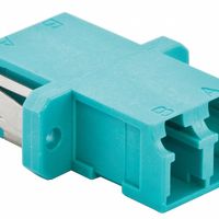
Fiber optic adapters work by aligning and connecting the ends of two fiber optic cables to enable the transmission of light signals between them. They ensure precise alignment of the fiber cores, minimizing signal loss and maintaining the integrity of the data being transmitted. These adapters typically consist of a sleeve or housing that holds the ferrules of the fiber connectors in place, allowing for a secure and stable connection.
Types of fiber optic adapters include:
1. **Simplex Adapters**: Connect a single fiber optic cable, used for single-channel communication.
2. **Duplex Adapters**: Connect two fiber optic cables, allowing for bi-directional communication, commonly used in applications requiring simultaneous transmission and reception.
3. **Quad Adapters**: Connect four fiber optic cables, often used in high-density networking environments.
4. **Hybrid Adapters**: Allow connections between different types of fiber optic connectors, such as SC to LC or ST to FC, facilitating compatibility between various systems.
5. **LC, SC, ST, FC Adapters**: These are named after the type of connector they support. LC (Lucent Connector), SC (Subscriber Connector), ST (Straight Tip), and FC (Ferrule Connector) are common types, each with specific design features for different applications.
6. **MTP/MPO Adapters**: Used for multi-fiber connections, supporting high-density applications like data centers.
7. **Bare Fiber Adapters**: Allow temporary connections of bare fiber to test equipment or other fibers without permanent connectors.
8. **Metal and Plastic Adapters**: Differ in material, with metal offering more durability and plastic being cost-effective.
These adapters are crucial in telecommunications, data centers, and networking environments, ensuring efficient and reliable fiber optic connections.
What is the purpose of fiber breakout kits and how are they used?
Fiber breakout kits are used to manage and protect the transition of fiber optic cables from a multi-fiber environment to individual fibers. Their primary purpose is to facilitate the safe and organized separation of fibers within a multi-fiber cable, such as a loose tube or ribbon cable, into individual fibers that can be terminated or spliced.
These kits are essential in environments where high-density fiber optic cables are used, such as data centers, telecommunications networks, and enterprise networks. They help in maintaining the integrity and performance of the fiber optic system by providing a structured way to handle the delicate fibers.
The breakout kit typically includes a protective housing or tubing, which encases the individual fibers once they are separated from the main cable. This housing prevents physical damage and minimizes the risk of signal loss due to bending or stress on the fibers. The kit may also include strain relief components to ensure that the fibers are not subjected to excessive tension.
To use a fiber breakout kit, technicians first strip the outer jacket of the multi-fiber cable to expose the individual fibers. The fibers are then carefully threaded through the breakout kit's protective tubing. Once secured, the fibers can be terminated with connectors or spliced to other fibers, depending on the network requirements.
Overall, fiber breakout kits are crucial for ensuring the reliability and efficiency of fiber optic networks by providing a methodical approach to fiber management and protection.
How do you install voice and data connectors on cables?
To install voice and data connectors on cables, follow these steps:
1. **Select the Right Tools and Materials**: Gather the necessary tools such as a cable stripper, crimping tool, punch-down tool, and the appropriate connectors (e.g., RJ-45 for Ethernet, RJ-11 for telephone).
2. **Prepare the Cable**: Use the cable stripper to remove about 1-2 inches of the outer jacket from the cable, exposing the twisted pairs inside. Be careful not to nick the wires.
3. **Organize the Wires**: Untwist the pairs and arrange them according to the wiring standard you are using (T568A or T568B for Ethernet). For voice cables, follow the standard color codes.
4. **Trim the Wires**: Cut the wires to an even length, leaving about half an inch exposed.
5. **Attach the Connector**:
- For Ethernet cables, insert the wires into the RJ-45 connector, ensuring each wire is in the correct slot. The clip should be facing down.
- For telephone cables, insert the wires into the RJ-11 connector.
6. **Crimp the Connector**: Use the crimping tool to secure the connector onto the cable. Ensure the pins pierce the wires for a solid connection.
7. **Test the Connection**: Use a cable tester to verify the connection is correct and functioning. This step ensures there are no shorts or miswires.
8. **Install the Jack or Patch Panel**: If connecting to a wall jack or patch panel, use a punch-down tool to secure the wires into the appropriate slots, following the color code.
9. **Label the Cables**: Clearly label each end of the cable for easy identification and troubleshooting.
10. **Secure the Installation**: Use cable ties or clips to organize and secure the cables, preventing strain on the connectors.
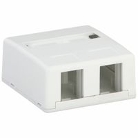
What are the benefits of using voice and data outlets, boxes, and faceplates?
Voice and data outlets, boxes, and faceplates offer several benefits in network and telecommunication setups:
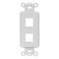
1. **Organization and Aesthetics**: These components help in organizing cables and wires, providing a neat and professional appearance. Faceplates cover outlets, hiding unsightly cables and connections, which enhances the overall aesthetics of a space.
2. **Protection**: Outlets and boxes protect the internal wiring from physical damage, dust, and moisture, which can lead to connectivity issues or equipment failure. Faceplates further safeguard the connections from accidental disconnections or environmental factors.
3. **Ease of Access and Maintenance**: They provide easy access points for connecting devices to a network, simplifying the process of adding or removing devices. This accessibility also facilitates maintenance and troubleshooting, as technicians can quickly identify and address issues.
4. **Scalability and Flexibility**: These components allow for easy expansion of network infrastructure. Additional outlets can be installed as needed, supporting future growth without significant overhauls.
5. **Standardization and Compatibility**: Using standardized outlets and faceplates ensures compatibility with a wide range of devices and cables, reducing the risk of connectivity problems and making it easier to integrate new technology.
6. **Safety**: Properly installed outlets and boxes reduce the risk of electrical hazards, such as short circuits or fires, by securely housing connections and preventing exposure to live wires.
7. **Cost-Effectiveness**: By protecting and organizing network infrastructure, these components can reduce the need for costly repairs and replacements, ultimately saving money over time.
8. **Improved Performance**: Well-organized and protected connections can lead to more reliable network performance, minimizing downtime and enhancing productivity.
