
Showing 0 products
Frequently Asked Questions
What does a valve terminal replace?
Individually mounted valves, each with its own supply, exhaust and pair of wires.
In a conventional arrangement, every solenoid valve on a machine is mounted separately. Each needs an air supply connection, an exhaust or silencer, and its own electrical cable back to the control system. Twenty valves means twenty of each.
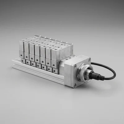
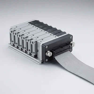
On a valve terminal, the valves sit on a common manifold that distributes supply air to all of them and collects all their exhaust, so there is one supply connection and one exhaust for the whole block. The electrical side is consolidated in the same way, into a single multi-pin connector or a fieldbus node.
What remains individual is only the working lines from each valve to its actuator, which have to exist in any arrangement.
The result is far less installation work, far less to go wrong, and a machine that can be built and tested faster - which is why terminals dominate modern machine building.
How does it improve machine response?
By letting the valves be mounted close to the actuators instead of in a remote cabinet.
A solenoid valve switches in milliseconds. What the machine actually experiences is much slower, because after the valve shifts, air must travel down the tubing and fill the cylinder before anything moves - and on a long run that dominates the cycle time completely.
Individually mounted valves are frequently grouped in a control cabinet for tidiness, which puts several metres of tube between every valve and its cylinder.
A valve terminal needs only one air supply and one cable, so it is practical to mount it on the machine itself, next to the actuators. The working lines become short, the volume to fill is small, and response improves substantially - often more than any change of valve would achieve.
That also reduces air consumption, since every actuation fills and then exhausts the tubing volume as well as the cylinder.
How is the number of stations decided?
From the number of actuators to be controlled and the functions they need, with an allowance for change - because adding stations later is a hardware job.
Each station carries one valve, and the valve's function must match what the actuator needs: a five-port valve for a double-acting cylinder, a three-port for a single-acting one or a vacuum generator, a three-position valve where a mid-stroke condition is required.
Mixed functions on one terminal are normal, which is one of its strengths.
The allowance for future change is the part worth thinking about. A terminal built to exactly the current requirement leaves no room, and adding a station later means either a new manifold section or a separate valve mounted elsewhere - which undoes some of the tidiness the terminal was bought for.
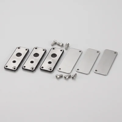
Specifying a few spare stations, fitted with blanking plates, is cheap at build time and saves a disproportionate amount of work later.
What flow capacity do the individual stations have?
It varies by terminal size and by station, and it must be checked against each actuator rather than assumed uniform.
A terminal is built around a manifold of a given size, and the valves fitted to it have a corresponding flow capacity. That is fine when all the actuators are similar. It becomes a problem when one large cylinder is fed from a terminal sized for small ones - the valve becomes the restriction and that cylinder is slow.
Some ranges allow different valve sizes on the same manifold, or offer stations with a higher flow, which solves it.
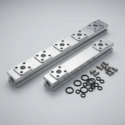
The other consideration is the common supply. If several large valves fire simultaneously, the manifold's supply passage and the single inlet must carry the combined flow, and a terminal whose individual stations are adequate can still be limited by its inlet.
Check both: the station flow against the largest actuator, and the inlet against the worst-case simultaneous demand.
Can different valve functions be mixed on one terminal?
Yes, and that flexibility is one of the main reasons to use one.
A single terminal can carry five-port valves for double-acting cylinders, three-port valves for single-acting actuators and vacuum generators, three-position valves with various centre conditions, and in many ranges proportional valves and vacuum modules as well.
Some ranges also allow individual stations to be supplied at a different pressure from the rest, which is useful where one actuator needs a lower pressure - a gentle clamp among firm ones, for example.
What has to be planned is the arrangement, because the physical layout and the electrical addressing follow the order of the stations. Rearranging them later means re-addressing the outputs as well as moving hardware.
So the station schedule - which function sits at which position - is worth getting right at design stage and documenting clearly, since it becomes the map everyone uses to maintain the machine.
How are the individual valves identified for maintenance?
By station number on the manifold, which is the practical advantage over a loom of individually wired valves.
On a terminal, each station has a fixed position and a corresponding output address. A fault reported as an output number maps directly to a physical position on the block, and the valve there can be examined or replaced.
That removes the tracing that individually mounted valves require, where finding the valve corresponding to a given output means following a wire.
Most terminals carry an indicator on each station showing the valve is energised, so the electrical and pneumatic sides can be separated at a glance - if the light is on and the cylinder has not moved, the problem is pneumatic.
Good practice is to label the stations with the machine function as well as the address, and to keep the station schedule with the machine documentation. A terminal with no schedule is considerably harder to work on than the wiring it replaced.
What happens if one valve fails?
It is replaced as an individual station without disturbing the others, provided the terminal is designed for it - which most are.
Valves on a terminal are normally retained by a couple of screws onto the manifold, with the porting made through the manifold face and the electrical connection made through the same interface. Removing one does not break any tubing or wiring.
The machine must be isolated and the terminal exhausted first, since the manifold is a common supply - which means a single valve failure generally requires the whole block to be depressurised, not just that station.
Some ranges allow individual station isolation, which is worth specifying where downtime is expensive.
Keep a spare valve of each function used on the machine. Because the valves are modular and identical within a function, one spare covers every station of that type, which is a far smaller stock than individually mounted valves of assorted makes would require.