Industrial Motor Contactors: The Essential Technical Guide
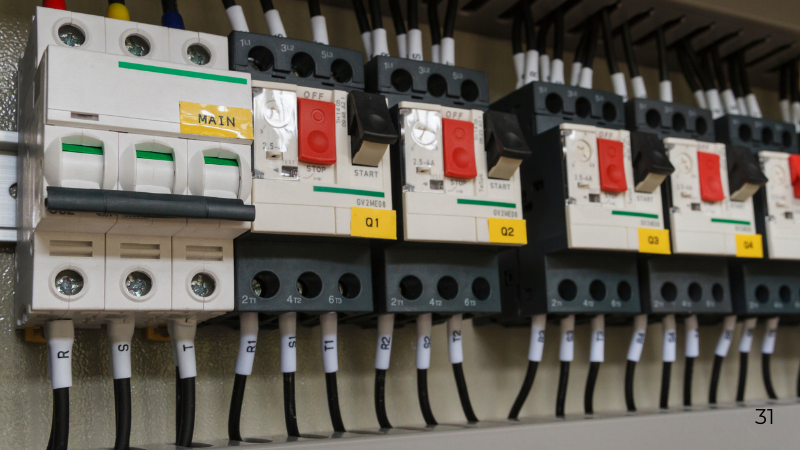
In industrial automation and power distribution systems, motor contactors play a critical role in controlling electric motors safely and efficiently. While often overlooked, these devices form the backbone of motor starters, switchgear assemblies, and automated control panels used across manufacturing, construction, HVAC, and utilities.
This guide explains what a motor contactor is, how it works, its key components, types, and how to select the right contactor for industrial applications.
✅ Key Takeaways: Motor Contactors at a Glance
🔹 Motor contactors are electrically controlled switches designed to handle high-current motor and power circuits.
🔹 They operate using electromagnetism, allowing low-voltage control signals to safely switch high-power loads.
🔹 Contactors are essential in motor starters, switchgear, control panels, pumps, compressors, and HVAC systems.
🔹 AC contactors are used for most industrial motors, while DC contactors serve battery and DC motor systems.
🔹 A contactor does not provide overload protection and must be paired with thermal overload relays and circuit protection devices.
🔹 Correct selection depends on current rating, voltage, coil voltage, utilization category (AC-3), and number of poles.
🔹 Properly selected contactors improve system safety, automation reliability, and motor lifespan.
What Is a Motor Contactor?
A motor contactor is an electrically operated switching device used to make or break a power circuit under normal operating conditions. It is primarily used to control electric motors, but also applies to lighting systems, heating elements, capacitor banks, and industrial loads.
Unlike manual switches, contactors allow remote and automated control, making them essential in systems integrated with:
-
Programmable Logic Controllers (PLCs)
-
Timers and sensors
-
Motor protection devices
-
Industrial automation networks
How Does a Motor Contactor Work?
Motor contactors operate on the principle of electromagnetism.
Step-by-Step Operation
-
Energizing the Coil
A control voltage (AC or DC) is applied to the contactor coil. -
Magnetic Field Formation
The energized coil generates a magnetic field. -
Contact Closure
The magnetic field pulls the armature inward, closing the main power contacts. -
Power Flow to the Motor
Electrical current flows to the motor or load. -
De-energizing the Coil
When the control signal is removed, the magnetic field collapses. -
Contact Opening
Spring force separates the contacts, safely interrupting power to the motor.
This rapid and repeatable process allows contactors to perform millions of switching operations in industrial environments.
Anatomy of a Motor Contactor: Key Components
Understanding the internal components helps with proper selection, installation, and troubleshooting.
Core Components
-
Coil (Electromagnet)
Generates the magnetic field. Must match the control voltage (e.g., 24V DC, 110V AC, 230V AC). -
Fixed Core and Moving Armature
Convert magnetic force into mechanical movement. -
Main Contacts
Heavy-duty contacts that carry motor current. -
Auxiliary Contacts
Low-current contacts used for signaling, interlocks, or PLC feedback. -
Arc Chutes
Extinguish electrical arcs formed during contact separation. -
Enclosure
Protects internal parts from dust, heat, and mechanical damage.
Types of Electrical Contactors
Contactors are classified by current type and application.
Common Contactor Types
| Contactor Type | Current Type | Typical Applications | Key Feature |
|---|---|---|---|
| AC Contactors | AC | Industrial motors, pumps, compressors | Optimized for AC arc suppression |
| DC Contactors | DC | Battery systems, cranes, DC motors | Specialized DC arc control |
| Capacitor Contactors | AC | Power Factor Correction (PFC) panels | Inrush current limiting resistors |
| Definite Purpose Contactors (DPC) | AC / DC | HVAC, refrigeration, lighting | Compact, cost-effective design |
Contactors in Industrial Motor Control Systems
In practice, contactors operate as part of a motor starter assembly, which combines control and protection.
Common Motor Starter Configurations
-
Direct-On-Line (DOL) Starter
Uses one contactor to connect the motor directly to the supply. -
Star-Delta (Wye-Delta) Starter
Uses three contactors to reduce starting current before full-load operation.
Why Contactors Must Be Paired with Protection Devices
A contactor controls power but does not protect equipment.
Required Protection Components
-
Thermal Overload Relays
Protect against prolonged overcurrent conditions such as motor stalls. -
Circuit Breakers or Fuses
Provide short-circuit and fault protection.
Together, these components ensure:
-
Electrical safety
-
Motor longevity
-
Compliance with industrial standards
How to Select the Right Motor Contactor
Correct sizing is critical for safe and reliable operation.
Electrical Selection Criteria
-
Rated Operational Voltage (Ue)
-
Rated Operational Current (Ie)
-
Utilization Category
-
AC-1: Resistive loads
-
AC-3: Standard for squirrel-cage motors
-
AC-4: Plugging and jogging applications
-
Mechanical and Control Factors
-
Coil voltage (must match control circuit)
-
Number of poles (typically 3 for three-phase motors)
-
Mounting type (DIN rail or panel mount)
Example:
A 20 kW three-phase motor typically requires a 3-pole AC contactor rated 40A, 400V, AC-3.
Advantages of Using Motor Contactors
-
Remote and automated motor control
-
High switching durability
-
Safe isolation for maintenance
-
Seamless integration with PLCs and automation systems
-
Reduced operational downtime
Maintenance and Common Failure Causes
Common Issues
-
Contact pitting or welding
-
Coil overheating due to incorrect voltage
-
Excessive arcing from worn contacts
Maintenance Best Practices
-
Inspect contacts regularly
-
Verify coil voltage and resistance
-
Tighten all terminal connections
-
Replace worn contact sets promptly
Frequently Asked Questions (FAQs)
What is the difference between a relay and a contactor?
A relay handles low-current control circuits, while a contactor is designed for high-current power circuits such as motors.
Can a contactor provide overload protection?
No. Overload protection must be provided by a thermal overload relay or motor protection circuit breaker.
What is the typical lifespan of a motor contactor?
Most industrial contactors are rated for 1–2 million mechanical operations, depending on load and duty cycle.
What causes contactor coil failure?
Incorrect voltage, continuous over-voltage, or mechanical issues preventing full armature movement.
Disclaimer
This article is provided for general technical and educational purposes only. It does not replace manufacturer documentation, professional engineering judgment, or local electrical codes. Installation, selection, and maintenance of motor contactors must be carried out by qualified electrical professionals. Always follow lockout/tagout (LOTO) procedures and applicable safety standards.
Related Posts

Sandblasting Sand: Why the Cheapest Abrasive Costs You the Most


Types of Pliers: Jaw Shapes, Grip and What Each Pair Is For