How to Size a Booster Pump: Flow, Head and Selection
By Cecillia Wehmeyer · 15 August 2026
Most booster pump problems start with the wrong question. Buyers ask how powerful the pump is, when the system only cares about two numbers.
Those numbers are flow and head. Get both right and a modest booster pump holds pressure across a whole building, and get them wrong and the largest machine on the shelf still leaves the top floor dry.
This guide walks the sizing calculation end to end, then covers the pump types, the suction-side limits and the wear parts that decide how long the installation lasts.
What a Booster Pump Actually Does
Pressure In, Pressure Out
A booster pump does not create water. It raises the pressure of water that already arrives at the inlet, which means the incoming supply pressure is part of the answer before you choose anything.
That single fact removes a lot of guesswork. You are not sizing for the full pressure the building needs, only for the shortfall between what the main delivers and what the furthest fixture demands. Measure the incoming pressure at its worst before anything else.
- Not a source: the booster pump adds pressure, it does not add water.
- Inlet matters: incoming main pressure is subtracted from the target.
- Shortfall only: the booster pump covers the gap, nothing more. - A generous main means a smaller pump. - A weak main pushes the duty point up fast.
Where Boosting Becomes Necessary
Tall buildings are the classic case. Plumbing engineers note that hotels, apartment blocks and offices all need boosting equipment to lift municipal pressure high enough to serve the upper floors. The taller the riser, the larger the share of the duty that pure lift takes.
Low-rise sites need it too, usually because the main is undersized, the site sits above the supply, or a long run has eaten the pressure before it reaches the building.
- Height: every floor costs pressure on the way up.
- Distance: long horizontal runs bleed pressure through friction.
- Weak mains: some networks simply arrive soft. - Irrigation and cooling towers add load on top of fixtures. - Peak morning demand exposes a marginal supply first.
Booster Pump Types You Will Meet
Single-Stage and Multistage
A single-stage booster pump has one impeller and suits modest pressure gains. Multistage booster pumps stack impellers in series, and each stage adds head without adding flow. That is the neat trick behind a tall, slim pump body that lifts water many storeys.
Most building services work runs multistage for that reason.
- Single-stage: simple, cheap, limited head.
- Multistage: stacked impellers, high head, same flow.
- Stage count: more stages means more pressure, not more litres.
Vertical and Horizontal Layouts
The choice here is usually plant room geometry rather than hydraulics. A vertical booster pump keeps the footprint small, and a horizontal machine trades floor space for easier access to the seal and bearings. Check the headroom above a vertical unit before ordering, because the impeller stack has to come out.
Compare the vertical booster pumps against the horizontal range before the plant room layout is fixed.
- Vertical: small footprint, tall clearance needed above.
- Horizontal: more floor area, simpler maintenance access.
- Skid packages: multiple pumps, manifolds and controls prebuilt.
Constant Pressure and Variable Speed Booster Pumps
Older systems ran at full speed and bled off the excess through a regulating valve, which was the standard approach until the early 1990s. Modern packages vary motor speed instead, so the booster pump produces only the pressure the building asks for.
The saving is real and well documented. Industry figures put the move from pressure-reducing valves to variable-speed drives at between 10 and 35 percent lower energy use.
- Valve control: full speed always, excess thrown away.
- Variable speed: output tracks demand in real time.
- Staging: extra booster pumps start only when flow climbs. - A constant pressure booster pump holds a set point across the whole flow range. - Power is roughly 85 percent of a pump's lifetime cost, so control strategy dominates the budget.
Step One: Work Out the Flow
The Fixture Unit Method
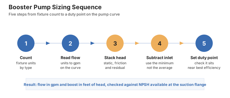
Commercial flow is not measured by counting taps. Each fixture type carries a fixture unit value, published in plumbing design references, and the totals convert to a design flow through a standard chart. Where two references disagree, plumbing designers take the higher count.
The logic is that not everything runs at once. A tower with hundreds of taps never sees all of them open together, so the fixture unit curve discounts the raw total into a realistic peak.
- Count fixtures: baths, basins, toilets, dishwashers, washing machines.
- Apply unit values: each fixture type has a published weighting.
- Read the curve: total fixture units convert to gallons per minute. - A worked industry example reached 1,092 fixture units for a 56-unit block. - That total translated to roughly 220 gallons per minute of design flow.
Design Flow Is Not Real Flow
The number you size on is a peak that rarely arrives. Building services data shows that high flow is needed only four to six hours a day, and that actual demand sits below a fifth of design flow for most of the day.
This is exactly why a single large booster pump is usually the wrong buy. It runs far from its efficient point almost all the time, cycles hard, and holds pressure badly. Several smaller machines staged in sequence track the real duty far more closely.
- Peak is brief: four to six hours out of twenty-four.
- Most hours are quiet: under 20 percent of design flow, 70 to 80 percent of the time.
- Split the duty: several smaller pumps beat one oversized machine.
Step Two: Build the Head and the Boost
The Four Parts of Head
Booster pump head is assembled from four separate quantities, and each one is measured or estimated independently before they are combined.
| Component | Symbol | What it represents | Typical value |
|---|---|---|---|
| Static head | HS | Vertical lift to the highest fixture | 10 to 12 feet per floor |
| Friction head | HF | Losses in pipe and fittings | 4 to 10 feet per 100 feet of pipe |
| Residual head | HR | Pressure needed at the furthest fixture | 20 to 40 psi |
| Inlet head | HI | Pressure already available at the main | Site measurement |
Static Head and the Booster Pump Riser
Static head is the pure lift, and it is the largest term in almost every tall building. Multiply the number of floors above the pump by the floor height, then convert that distance into pressure. Count only the floors above the pump, since a basement plant room serves everything overhead.
Pressure and head convert through a fixed factor, so the arithmetic never changes.
- Measure the rise: floors above the booster pump, not the total building height.
- Use the factor: 1 psi equals 2.31 feet of water at 68 degrees Fahrenheit.
- Adjust for fluid: divide 2.31 by the specific gravity for anything but cold water.
Friction Head and Fittings
Friction is the loss along the pipe walls plus the turbulence the water creates itself. It grows sharply with velocity, and doubling the flow through a given pipe size quadruples the loss. Narrow pipe therefore punishes the pump twice, once on peak flow and again on every running hour.
Fittings matter more than most estimates allow. A common rule of thumb adds 5 percent of the longest pipe run to cover elbows, valves and tees.
- Per-length loss: 4 to 10 feet of head per 100 feet of pipe.
- Fittings uplift: add 5 percent of the longest run.
- Velocity penalty: double the flow and friction goes up fourfold. - Wider pipe is often cheaper than a bigger booster pump. - Fix the pipe route before increasing the duty point.
Subtracting the Inlet Pressure
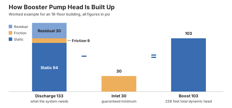
Add static, friction and residual together and you have the discharge pressure the system needs.
Subtract the guaranteed minimum inlet pressure and what remains is the boost the pump must provide.
Use the minimum inlet figure, never the average.
A booster pump sized on a good day will fail on the worst one.
| Step | Example figure |
|---|---|
| Static head HS | 94 psi |
| Friction head HF | 9 psi |
| Residual head HR | 30 psi |
| Required discharge | 133 psi |
| Minimum inlet HI | 30 psi |
| **Boost required** | **103 psi** |
| **Total dynamic head** | **238 feet** |
NPSH, Cavitation and the Suction Side
NPSH Available and NPSH Required
Discharge is only half the picture. The suction side decides whether the booster pump survives, and the measure that governs it is net positive suction head.
Pump standards bodies define the available figure as the head at the pump inlet above the vapour pressure of the liquid at its working temperature. The required figure comes from the manufacturer and states the minimum the pump needs to perform as published. Hot water lowers the available figure sharply, because vapour pressure climbs with temperature.
- NPSHA: what the system offers at the suction flange.
- NPSHR: what the pump demands to hit its curve.
- Margin: available must exceed required, with room to spare. - Standard atmospheric pressure at sea level is 14.7 psi absolute. - Suction pipe friction eats into the available figure before the water arrives.
The Three Percent Rule
Inside the impeller eye the head dips before the vanes add energy. If it dips below vapour pressure the water flashes to vapour, and those bubbles collapse violently in the higher pressure further along the impeller.
That collapse is cavitation, and it erodes metal. Pump standards define the required figure at the point where head has already dropped 3 percent, a criterion adopted back in 1932 because it was the smallest drop that could be measured reliably.
- Warning sign: gravel-in-the-pump noise under load.
- The published number: the point of 3 percent head loss, not a safe operating limit.
- Add margin: modern high-speed pumps need headroom above that point.
Preferred and Allowable Operating Regions
Every impeller has one flow where the water meets the vanes cleanly, and that point sits near best efficiency. Move away from it and the flow separates, recirculates and loads the shaft unevenly.
Standards split this into a preferred band around best efficiency and a wider allowable band where service life is still acceptable.
- Preferred region: efficiency and reliability essentially intact.
- Allowable region: wider, tolerable, not ideal.
- Beyond both: vibration, local cavitation and shortened life. - Required suction margin rises as you move away from best efficiency. - A staged system keeps each running pump nearer its sweet spot.
Impellers, Seals and Booster Pump Upkeep
Booster Pump Impeller Wear and Cartridges
The impeller is the part that does the work and the part that pays for any suction-side mistake. Cavitation pits the vane surfaces, and abrasives round off the edges until head falls away quietly. Nothing announces the loss, which is why it usually goes unnoticed for months.
Falling pressure at unchanged speed is the symptom worth watching. Replacement impellers and cartridge assemblies restore the original duty point without a new pump.
- Pitting: cavitation damage, usually on the vane inlet.
- Erosion: grit and scale wearing the profile smooth.
- Symptom: head drops while speed stays the same.
Seal Kits and Gaskets
Booster pump seals fail before impellers do, and dry running is the usual cause. Any weeping at the shaft is a warning rather than a nuisance.
Keeping a seal kit on the shelf turns a plant room emergency into a scheduled hour of work.
- Dry running: the fastest way to destroy a seal face.
- Weeping: early failure, not normal seepage.
- Stock spares: seal kits and gaskets cost far less than downtime.
Motors, Controls and Staging
The booster pump motor is sized from the duty point, not from the pipe size or a rule of thumb. Oversizing wastes energy every hour the booster pump runs, because power dominates lifetime cost.
Controls decide how well several booster pumps share the load. Good staging brings machines in and out so the running set stays near best efficiency.
- Motor sizing: set the booster pump motor from the duty point only.
- Protection: flow protectors guard against dry running.
- Staging logic: lead and lag rotation spreads the running hours.
Frequently Asked Questions About Booster Pumps
How do I size a booster pump?
Work out the design flow from fixture unit counts, then build the head from static lift, friction loss and the residual pressure needed at the furthest fixture. Subtract the minimum inlet pressure from that total, and the remainder is the boost your pump must deliver at the design flow.
What is the difference between a single-stage and a multistage booster pump?
A single-stage booster pump uses one impeller and suits modest pressure gains. A multistage pump stacks impellers in series so each one adds head at the same flow rate, which is why building services packages are usually multistage.
Why does my booster pump keep cycling on and off?
Cycling almost always means the booster pump is too large for the demand it actually sees. Real flow sits below a fifth of design flow for most of the day, so a single oversized machine hunts around its set point instead of holding it steadily.
What causes cavitation in a booster pump?
Cavitation happens when the pressure at the impeller eye falls below the vapour pressure of the water. Vapour bubbles form, then collapse in the higher pressure region of the impeller, and the repeated collapses erode the metal.
Is a variable speed booster pump worth the extra cost?
In most cases yes, because power is roughly 85 percent of a pump's lifetime cost. Published industry figures put the saving from replacing pressure-reducing valve control with variable-speed drives at between 10 and 35 percent.
Conclusion
Size a booster pump in three moves. Fix the design flow from fixture units, stack the head from static lift, friction and residual pressure, then subtract the guaranteed inlet pressure to get the boost.
Choose the machine only after that. Multistage for high head, vertical where floor space is tight, variable speed wherever demand swings through the day.
Then protect the investment. Give the suction side proper margin, keep the running pumps near best efficiency, and hold seal kits and gaskets in stock so a worn seal never becomes a lost day.
Related Posts
Sandblasting Sand: Why the Cheapest Abrasive Costs You the Most


Types of Pliers: Jaw Shapes, Grip and What Each Pair Is For