
Showing 0 products
Frequently Asked Questions
What are these valves used for in a circuit?
As inputs - the pneumatic equivalent of limit switches, buttons and sensors.
A pneumatic control circuit needs to know things: that a cylinder has reached the end of its stroke, that a workpiece is in position, that an operator has pressed a start control.
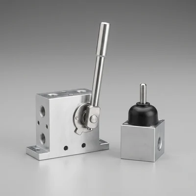
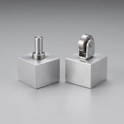
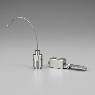
In an electrically controlled machine those facts come from switches and sensors wired to a PLC. In a pneumatic circuit they come from these valves. A roller valve mounted where a cylinder's rod end reaches it is a limit switch; a hand lever valve is a control station; a whisker valve at the edge of a conveyor detects a passing part.
Each produces a pressure signal when actuated, and those signals pilot the main valves that drive the machine.
So they are not usually handling working flow - they are generating signals, which is why they can be small and why their flow capacity is rarely the governing specification. What matters is the actuator, the force required and the reliability of the switching.
Why use pneumatic sensing rather than electrical?
Because it needs no power, no wiring and no controller - and because it works where electricity is difficult.
A simple clamping, feeding or indexing function can be built entirely from a few valves and some tube. There is no panel, no PLC, no cabling, no programming and nothing to configure. For a jig, a bench fixture or a small standalone device, that is genuinely simpler and cheaper than the electrical equivalent, and anyone with basic skills can maintain it.
Hazardous areas are the other case. A pneumatic sensing circuit contains no electrical energy at all, so there is nothing to certify and no ignition source - which in an explosive atmosphere removes a substantial cost and complication.
Wet, washdown and high-pressure cleaning environments suit them too, since a mechanical valve tolerates water in a way an electrical sensor requires protection to survive.
Against that, electrical sensing is far more flexible, easier to diagnose and better suited to anything complex - which is why most machinery uses it.
How much force is needed to operate one?
It varies widely by type, and matching it to what is available is the main selection question.
A hand lever valve is designed to be operated by a person and needs a force an operator can comfortably apply repeatedly. A roller valve actuated by a machine movement can take a firmer push, since the mechanism provides it. A whisker valve is designed for very light contact, so a fragile workpiece can trip it without being marked or deflected.
Get this wrong in either direction and it fails. Too much force required and a light workpiece passes without operating the valve, or an operator finds the control tiring. Too little and the valve is actuated by vibration or by incidental contact, producing false signals.
Manufacturers publish actuating force and travel. Compare them against what the application actually provides - the mass and speed of the part, or the ergonomics of the operator position - rather than choosing on port size and appearance.
Are these valves suitable for safety functions?
Some are made specifically for safety duties, but an ordinary mechanical valve is not a safety component simply because it is mechanical.
Safety-rated pneumatic devices exist - emergency stop valves, safety exhaust and dump valves, two-hand control units and interlock valves - and they are designed, tested and certified against the relevant machinery safety standards, with defined failure behaviour and often redundant construction.
A standard roller or lever valve is not. It will work reliably in normal service, but it has no assessed failure mode, no diagnostic coverage and no certification.
So where a valve forms part of a safety function - guard interlocking, emergency stop, two-hand control - specify a device rated for it and integrate it according to the standard, including the required performance level.
Using a general purpose valve because it is mechanically similar is a common and serious error, and it will not survive an assessment.
What mounting arrangements are available?
Body mounting, panel mounting and sub-base mounting, chosen by how the valve is positioned relative to what actuates it.
Body-mounted valves have threaded holes or a flange on the valve body and are bolted to a bracket wherever the actuation occurs - typical for roller and plunger valves positioned against a moving part.
Panel-mounted valves fix through a hole in a control panel with a nut, presenting the lever or button on the operator's side - the arrangement for hand valves at a control station.
Sub-base mounting puts the port connections in a separate base plate, so the valve can be removed and replaced without disturbing the tubing. That matters where a valve is expected to wear out, since replacement becomes a two-screw job.
For mechanically actuated valves, the critical dimension is the relationship between the mounting face and the actuator, since that determines the position and travel of the operating member relative to the machine.
How are they adjusted and set up?
By setting the position of the valve relative to the actuating member so the full actuating travel is used - without over-travelling it.
Every mechanically actuated valve has an actuating travel: the distance the plunger, roller or lever must move to switch it, and a maximum travel beyond which it will be damaged.
Setting it too far away means the machine part does not push it far enough and the valve switches intermittently or not at all. Setting it too close means the part drives the actuator beyond its limit, bending the plunger or breaking the mechanism - and this is the more common failure, because it looks safer to be sure of actuation.
So the valve is positioned so the movement takes the actuator comfortably through its switching point and stops short of its maximum. On roller valves, an overtravel or idle-return type accommodates a part that continues past.
Check the setting after any mechanical work; these are the components most likely to be disturbed.
What causes them to fail in service?
Wear of the actuating mechanism, contamination, and mechanical over-travel - in roughly that order.
The actuator is a moving mechanical part contacted many times an hour by a machine member, so rollers, plungers and their bearings wear. As they do, the switching point shifts slightly, and a valve that was reliably actuated begins to switch late or intermittently.
Contamination is the next: dust, coolant and swarf work into the actuator mechanism and stiffen it, so the valve either fails to return or requires more force than the machine provides.
Over-travel damage comes from setting the valve too close, or from a machine that has moved slightly on its mountings so the part now drives the actuator too far.
Because these valves are the inputs to the circuit, their failure presents as the machine behaving oddly rather than as an obvious valve fault - so when diagnosing an erratic pneumatic sequence, checking the input valves first is usually the quickest route.