Suspended Ceiling Grid: Modules, Duty Ratings and Installation Rules

By Angela Siniscalo · 30 July 2026
Most people looking up at an office ceiling see the tiles. The suspended ceiling grid holding them carries the load, sets the module and decides whether the finished plane looks flat.
Get the suspended ceiling grid wrong and no tile will rescue it.
What a Suspended Ceiling Grid Actually Does
A suspended ceiling grid is a structural system with a load rating, not a decorative trim.
Armstrong's installation instructions are explicit on this point. Every grid component must be rated for load under ASTM C635 and ASTM E3090.
The parts that carry the load
- Main beams, also called main runners or main tees, span the room and take the hanger wires.
- Cross tees clip into the mains at right angles and divide the space into modules.
- Hanger wires tie the mains back to the structure above.
- Wall molding finishes the perimeter and carries the border panels. - It is not a load-bearing component in most systems. - It still needs fixing to the wall every 16 to 24 inches on centre.
Face widths and what they signal
North American systems come in two exposed face widths. Both must meet ASTM C636 plus whatever local code adds.
- 15/16 inch is the wider, more forgiving face and the default for square lay-in panels.
- 9/16 inch gives a finer sight line and suits tegular panels with a stepped edge. - Square lay-in panels have no edge cuts and sit above the grid. - Tegular panels drop the tile face below the grid line.
Face width is not only a looks decision. The tile edge detail has to match the suspended ceiling grid you bought.
Suspended Ceiling Grid Modules and Layouts
Module size is the first suspended ceiling grid decision. It is fixed by where the mains and cross tees land.
The two standard imperial layouts
| Layout | Main beam spacing | Cross tee arrangement | Resulting module |
|---|---|---|---|
| Standard 2 ft x 4 ft | 48 in on centre | 4 ft cross tees at 90 degrees, every 24 in | 24 in x 48 in |
| Standard 2 ft x 2 ft | 48 in on centre | as above, plus 2 ft cross tees at the midpoints | 24 in x 24 in |
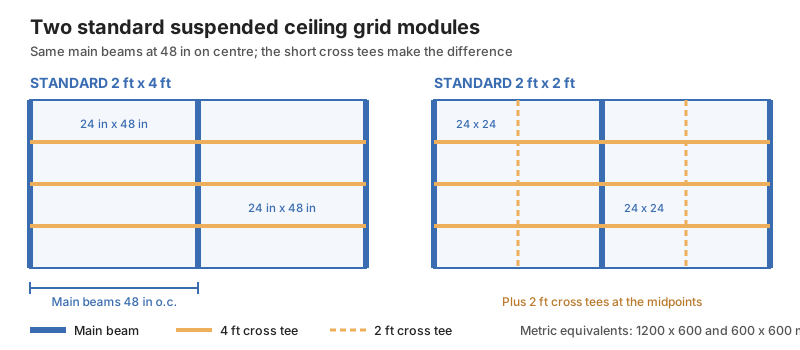
Both layouts share the same skeleton. The 2 ft x 2 ft module is simply the 2 ft x 4 ft module cut in half by an extra run of short cross tees. Nothing else about the suspended ceiling grid changes.
The metric equivalents
Outside North America the same system arrives in millimetres. The FIS guidance to BS EN 13964 describes a lay-in ceiling as an inverted tee system with a visible width of 24 mm or 15 mm, on 600 x 600 mm or 1200 x 600 mm modules.
Metric main tee load data is published against a 1200 mm span. That span is what produces the 600 x 600 mm suspended ceiling grid configuration.
Cross-hatch and running bond layouts
- Cross-hatch layouts widen cross tee spacing until it equals or exceeds the hanger spacing, so those tees must match the mains in load capacity.
- Running bond layouts stagger the openings between rows, leaving single cross tees in rout holes that must be reinforced to meet code connection strength.
Duty Ratings: How ASTM C635 Classifies a Grid
Three duty classes cover almost every commercial suspended ceiling grid sold.
The three classes and their loads
| Duty class | Load rating | Metric equivalent |
|---|---|---|
| Light Duty | 5 lb per linear foot | 7.4 kg/m |
| Intermediate Duty | 12 lb per linear foot | 17.9 kg/m |
| Heavy Duty | 16 lb per linear foot | 23.8 kg/m |
A main tee is tested on a 48 inch simple span and loaded to its class. It may not deflect more than L/360 of the span.
What the deflection limit really measures
At a 48 inch span, L/360 works out at roughly 1/8 inch. That is the point at which sag becomes visible to the eye, which is why the criterion exists.
USG is blunt about this in its technical guide. The duty rating is an aesthetic control rather than a safety factor, despite decades inside seismic ceiling standards.
A tee that cannot hold its load within the allowable deflection does not fail outright. ASTM C635 requires it to be reclassified downward. An Intermediate tee simply becomes a Light Duty tee, and the suspended ceiling grid it belongs to drops a class with it.
When seismic codes take the decision away
The International Building Code, ASCE/SEI 7 and ASTM E580 work together here. Between them they set a floor on which suspended ceiling grid you may use.
- Seismic Design Categories A and B carry no duty requirement.
- Category C requires an Intermediate Duty main tee.
- Categories D, E and F require Heavy Duty. - Main tee to cross tee intersections must hold at least 180 lb. - The vertical wire connection to the structure must sustain at least 100 lb.
Tightening hanger spacing can lift a tee's actual load capacity. It does not change the printed duty classification.
Suspension Rules That Keep the Grid Level
A correctly rated suspended ceiling grid still sags if the wires are wrong.
Hanger wire specification
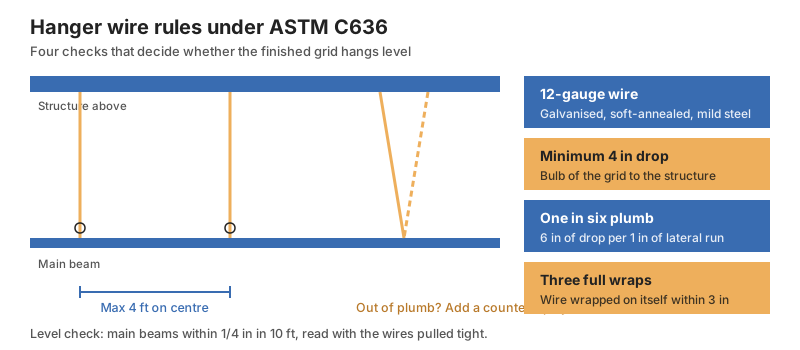
- Use a minimum 12-gauge galvanised, soft-annealed, mild steel wire.
- Allow a minimum drop of 4 inches from the bulb of the grid to the structure.
- Space wires no more than 4 feet on centre along the main beams.
Plumb, splay and wrap rules
Each wire must sit within one in six of plumb, meaning at least 6 inches of vertical drop for every 1 inch of lateral movement. Where that is impossible, ASTM C636 calls for an equally sloped counter-splay wire in the opposing direction.
Every wire also has to be wrapped around itself at least three full turns within 3 inches. On fire-rated mains, a wire belongs within 3 inches of each fire expansion relief cut-out.
Level and squareness checks
Two checks catch almost every out-of-true suspended ceiling grid before the tiles go in.
- Main beams must be level to within 1/4 inch in 10 feet, read below the hanger points with the wires pulled tight.
- Measure the opposite diagonals inside one grid opening; matching readings mean it is square.
Room Layout, Borders and Plenum
Layout decisions made in the first hour set the quality of the finished suspended ceiling grid.
Border panels
Border width is what makes a suspended ceiling grid look designed rather than improvised.
- Keep border panels at no less than 10 inches wide wherever the room allows.
- Give the opposite wall an identical border so the room reads balanced.
- Divide the room dimension by the panel length, split the remainder across two borders, and add a panel back if they come out narrow.
Plenum clearance
Leave at least 3 inches between the grid and anything above it. Old ceilings, ducts, pipes and cable trays all need that gap. A panel has to tilt into the opening without fouling them.
What the European standard leaves out
BS EN 13964 was last revised in 2014 and carries designated status. Covered products should arrive with conformity marking and a declaration of performance.
- External ceilings fall outside the standard entirely.
- So do ceilings subject to water penetration requirements.
- Heavy duty walk-on ceilings are excluded as well.
Any of those three jobs needs a suspended ceiling grid qualified some other way.
How to Specify a Suspended Ceiling Grid
An order that says "T-bar and tiles" leaves five suspended ceiling grid decisions to somebody else.
The fields worth writing down
- Governing standard, whether ASTM C635 and C636 or BS EN 13964.
- Module size, in the unit your drawings use.
- Exposed face width, either 15/16 and 9/16 inch or 24 and 15 mm.
- Duty class, checked against the seismic design category.
- Finish and material, since aluminium and stainless suit wet or non-magnetic rooms.
- Tile edge detail, because it has to match the grid you bought.
Where the grid meets everything else
Compare stocked profiles in the ceiling tile grid range before fixing the module. Availability often decides the layout.
Then match the ceiling tiles and panels to the face width you chose. The ceiling tile tools and hardware category covers the clips, wires and trims that finish the job.
Frequently Asked Questions About Suspended Ceiling Grids
What are the standard suspended ceiling grid sizes?
There are two in each measurement system. Imperial work uses 24 in x 48 in and 24 in x 24 in modules, while metric markets use 1200 x 600 mm and 600 x 600 mm.
Is a drop ceiling grid the same as a suspended ceiling grid?
Yes, the two names describe the same system. "Drop ceiling" is the common North American term. "Suspended ceiling" is what the standards and most other markets use.
Which duty class does my project need?
That depends on the seismic design category rather than preference, with Category C calling for Intermediate Duty and Categories D through F calling for Heavy Duty.
Conclusion: Specify the Grid, Not Just the Tile
A suspended ceiling grid is the only part of the assembly with a published load rating, a deflection limit and a code-driven duty class. The tile that sits in it is the finish.
Name the standard, the module, the face width and the duty class of the suspended ceiling grid on the order.
Do that and the grid arrives right, the wires go up right, and the ceiling reads flat. Skip it, and someone at the loading bay decides for you.
Related Posts

Drywall Anchor Guide: Types, Load Ratings and Safe Fixing